48
Instructions for installation and use of low temperature kits
SPLIT RACK AIR CONDITIONER USER MANUAL
UM.ICUBE2.0-SRAC.SG.0822 August 2022 www.eaton.com
6.4 Schematic diagram of system with low temperature kits
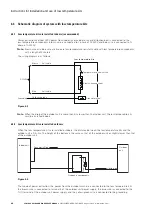
6.4.1 Low temperature kits are installed indoors (recommended)
Power extraction method: 220V power from indoor (user cabinet or user distribution box) is connected to the
low temperature components, brown wire is connected to L phase of AC220V, and blue wire is connected to N
phase of AC220V.
ote:
N
Brown wire and blue wire are two-core low-temperature resistant cable with low temperature components,
with a length of 5 meters.
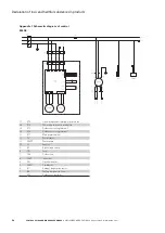
The wiring diagram is as follows:
Cryogenic component
Temperature control switch
Electric heating sheet
Yellowish green
AC220V
Grounding
Ground terminal
Brown
Blue
Self cable
Self cable
Low temperature kits
Figure 6.3
ote:
N
When the drop of the outdoor unit is more than 5 m lower than the indoor unit, the low temperature kits
must be installed indoors.
6.4.2 Low temperature kits are installed outdoors
When the low temperature kits are installed outdoors, the distance between the low temperature kits and the
outdoor unit is 0.5~2m. The height of the bottom is the same as that of the outdoor unit or slightly lower than that
of the outdoor unit.
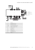
Indoor unit
Outdoor
unit
Cryogenic components
Penumatic Pipe
One-way valve
Liquid pipe
Figure 6.4
The mode of power extraction: the power from the outdoor machine is connected to the low temperature kits,
the brown wire is connected to terminal 3 of the outdoor unit power supply, the blue wire is connected to the
N (1) terminal of the outdoor unit power supply, and the yellow-green wire is connected to the grounding

