8
Unit installation
SPLIT RACK AIR CONDITIONER USER MANUAL
UM.ICUBE2.0-SRAC.SG.0822 August 2022 www.eaton.com
The air outlet
side is greater
than 2000mm.
The air inlet
side is greater
than 2000mm.
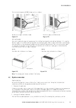
Figure 2.4
4-M8X30 anchor bolts
4-M8X30 anchor bolts
Figure 2.5
Figure 2.6
Schematic diagram of outdoor unit positioning
Unpacking of the unit:
After the unit is transported to the floor or foundation of the installation unit, remove the package and remove the
desiccant from the unit.
Release nitrogen:
Open the gas circuit and liquid circuit globe valves of the indoor unit with 5mm inner hexagon spanner,
respectively, and connect the pressure gauge to exhaust on the gas path needle valve and the liquid path needle
valve respectively. Please check the vacuum section(2.8) for specific valve location. The complete nitrogen release
operation must be carried out after the copper pipe connection of the indoor unit is completed. Open the cutoff
valve of the indoor unit and outdoor unit, and then connect the pressure gauge to exhaust, otherwise more frozen
oil can spew out, or the nitrogen discharge operation will be release in the outdoor unit.
NOTES
- If there is no nitrogen released, please contact Eaton Corporation.


