22
XCHARGEIN MOBILITY INSTALLATION MANUAL
MN191005EN April 2021 www.eaton.com
00 Title
6.5 Configuration of the charging current
xChargeIn Mobility has advanced settings. This section provides further details about possible configurations
of the control unit (CU). These main configurations enable the user to do the following:
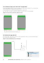
1. Limit the charging station current to 16 A.
2. Balance load between two “back to back” xChargeIn Mobility 22 kW AC EV chargers. This configuration is often
adopted when two units are mounted on the same floor mounting frame. To balance the load across multiple
charging stations please refer to xChargeIn Balancer installation manual available from the Eaton website
www.eaton.com.
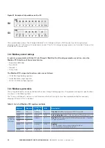
3. Switch the charging station off (no power delivered).
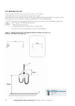
Figure 17. Location of the xChargeIn Mobility CU
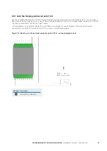
It is possible to set these configurations via the CU as shown in the following figure.
Power +24 V
9
Pr
ot
ectiv
e Ear
th
8
P1_SM3_CP
7
P1_SM3_PP
6
P2_PM3_CP
5
Ener
gy Met
er
4
Enabled
3
Br
eak
er Stat
e
2
Emer
gency St
op
1
CAN Lo
w
18
CAN High
17
P1_SM3
16
P2_PM3
15
P3_T23
14
Rela
y Stat
e
13
Regulat
e Out
12
11
Regulat
e In
10

