18
XCHARGEIN MOBILITY INSTALLATION MANUAL
MN191005EN April 2021 www.eaton.com
00 Title
When dimensioning the line circuit breaker, the increased ambient temperatures in the control cabinet
must also be considered. Under certain circumstances, this can make a reduction of the charging current
specification necessary in order to increase the system availability.
The nominal current must be determined in accordance with the type plate data in coordination with the
desired charging power and the supply line.
I
(circuit breaker)
≤ I
(supply line)
≤ I
(nominal current)
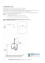
Figure 12. xChargeIn Mobility charging station wiring
Please follow the connection diagram for each charging station. Please note that the 3.7 kW and 7.4 kW models are for
single-phase connection only.
Each charging station must be connected via a separate RCD/fault-current circuit breaker. No other
consumers may be connected to this circuit.
The circuit breakers and the power cable minimal cross-sections are overvalued to ensure the functionality
of the charging station with higher temperatures.
During installation, other important issues such as “cascading” of RCDs and selection of a suitable line
circuit breaker must be considered.
It is permitted to supply the 16 A terminal, under the following conditions:
•
If the temperature where the circuit breaker is located does not exceed its reference value.
•
If the circuit breaker can withstand the maximum current without tripping under the worst temperature
conditions.
•
Please refer to local standards for further details.
Number Description
1
xChargeIn Mobility charger
2
Residual Current Device (RCD)
3
Circuit breaker


