IQ DP-4000
SECTION 3- OPERATOR PANEL
3.1 INTRODUCTION
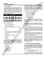
This section describes the operator panel of the IQ DP-
4000. The discussion of the operator panel contains the
following sections:
•
pushbuttons
•
display window
•
LEOs
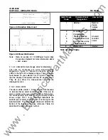
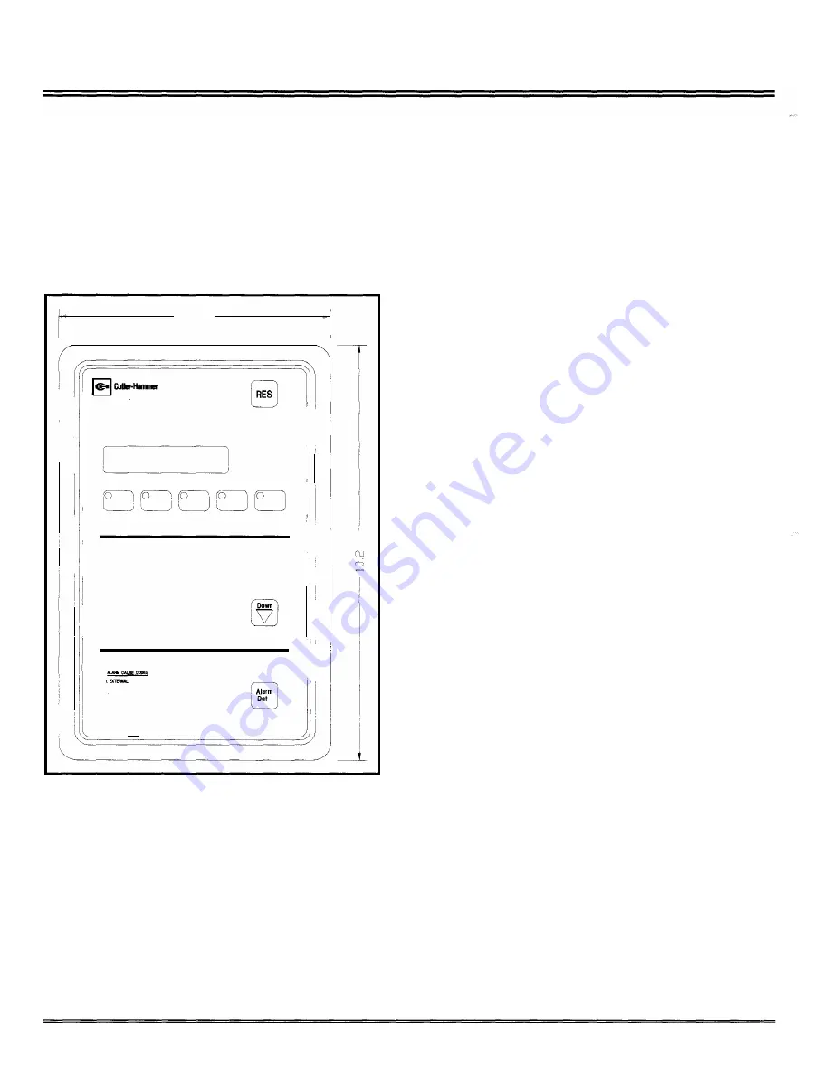
The operator panel is shown in Figure 3. 1
6.720
I
II
Westrn�ouse
@
10
DP-4000
Reset
I �I
0
Alarm
1
0
Alarm
2
0
Units
I.
0
Kilo-Units
0
Mega-Units
. I
II
Metered
'!.THO
Demand
Mmum
Maximum
i I
0
lA Amps
0
Watts
0 Ia
Amps
0
Vars
[iJ
0 lc
Amps
0
VA
0
VH Volts
0
Power Factor
Up
0
Va.c Volts
0
Frequency
0
Vc-• Volts
0
Watt-Hours
·I
0
v
...
Volts
0
Var-Hours
0
v
...
Volts
0
VA-Hours
0 Ye-o
Volts
2.0'I'ERYOLTAGE
SIJIIEAYCl.TAGE
of.PHAIIEI.IeAI.ANCE
a
I
6.YOI.TAII:PW.SELOBS
8.CI,IIBTPHA8EL088
7.PHASERE'IERSAL
.
"""""""
Figure 3. 1 Operator Panel
3. 1. 1 Pushbuttons
Ill
·
I'
li
Ill
0
.I
c'l
111
.II.
I' I �I
The operator panel has nine membrane pushbuttons.
They are:
•
Reset. After an alarm event, the Reset pushbutton
allows you to reset the alarms. The Reset
pushbutton is the red button marked RES, located
in the upper right-hand corner of the faceplate.
•
Up/Down Step Display. The Up/Down pushbuttons
step through the items that the IQ DP-4000
monitors. If you press the Up and the Down buttons
8
TD1 7548A
at the same time, the INCOM network address for
your unit appears in the Display W indow. It monitors
the following items:
•
lA Amps
•
18Amps
•
lc Amps
•
VA-s Volts
•
Ve-e Volts
•
Vc-A Volts
•
VA-N Volts
•
Va-N Volts
•
Vc-N Volts
•
Watts
•
Vars
•
VA
•
Power Factor (apparent and displacement)
•
Frequency
•
Watt-Hours
•
Var-Hours
•
VA-Hours
Each time you press the Up or Down pushbuttons, the
LED to the left of the selected item illuminates. At
the same time, the present operating value
corresponding to that item is in the display window.
•
Alarm
Data
pushbutton .
The
Alarm
Data
pushbutton, located on the bottom right of the
operator panel, allows you to toggle between Alarm
1 , Alarm
2,
and presently metered values. A blinking
LED indicates you are viewing the snapshot (data
saved at the time an alarm condition occurred for
that particular alarm. An LED that is constantly
illuminated indicates an active alarm condition for
that particular alarm . (Piease note that the Alarm
LED will always blink when being viewed, even for
an active alarm).
If you press the Alarm Data button before there has
been an alarm condition, no light appears beside
the Alarm.
•
Monitor pushbuttons. The Monitor pushbuttons,
located in a row just below the LED display window
are:
www
. ElectricalPartManuals
. com


