IQ DP-4000
SECTION 4 - INSTALLATION AND STARTUP
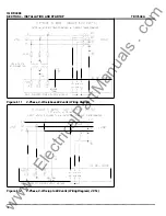
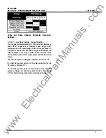
TD1 7548A
3 PHASE
4
WIRE (ABOVE
600
VOLTS)
EX TERNAL VOLTAGE TRANSFORMERS
&
CURRENT TR.4NSFORMERS
N
L3
UNE
L2
L1
FUSE
WYE
CONNECTION
t
FUS
�
� B�
NEUTRAL
TERM.
SELF-POWERED POWER SUPPLY MODULE
6
6
HlC Hl B HlA
LOAD
I
10 DP-4000
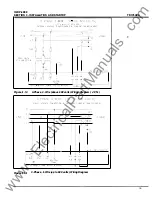
Figure 4.15
3-Phase, 4-Wire (above
600
volts) Wiring Diagram
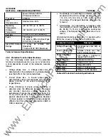
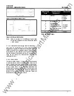
4.5 INITIAL STARTUP
Follow the initial startup procedure before and when you
first apply AC power to the IQ DP-4000. Use this as a
checklist to be sure you do not miss any steps.
AwARNING
THE FOLLOWING STARTUP PROCEDURES M UST
BE PERFORMED ONLY BY QUALIFIED PERSONNEL
WHO ARE FAMILIAR WITH THE IQ DP-4000 AND ITS
ASSOCIATED ELECTRICAL AND/OR MECHANICAL
EQUIPMENT. FAILURE TO OBSERVE THIS CAUTION
CAN RESULT IN SERIOUS INJURY OR EVEN DEATH.
20
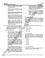
4.5.1 During Initial Power Application
To apply AC power to the IQ DP-4000 for the first time:
1 . Verify that the AC power is off.
2. Verify that the line-to-line voltages fall within the
correct range, as noted on the wiring plan drawing.
3. Check that all wiring is correct according to the
wiring plan drawings.
4. When possible, lockout any foreign power sources
and disable the IQ DP-4000 until all other machines
or processes are started and thoroughly checked.
5. Restore AC power and verify the operator panel
functions, after an initial delay, as follows:
•
The lA Amps LED lights.
•
The Display Window shows the actual line
phase A amperes.
6. Set all Setpoint Switches according to the Master
Setpoint Record Sheet (Appendix B).
www
. ElectricalPartManuals
. com

