


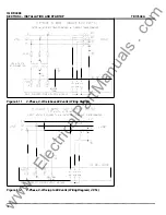
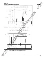


IQ DP-4000
SECTION 5 - PROGRAMMING THE IQ DP-4000
phase rotation of the metered voltages to the selected
phase sequence of the system (see Section 5.8) , and
activates the alarm if the order of the phases does not
correspond for longer than the alarm delay (see Section
5.1 2.1 0) . See Table 5.0 for setting this option.
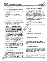
Alarm
1
Alarm 2
Position
SW6
No. 7
SW7
No. 7
OFF disables Activate on
Phase Reversal
ON enables Activate on
Phase Reversal
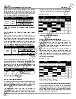
Table 5.0 Activate on Voltage Phase Reversal
Settings
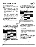
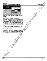
5. 12.8 Activate on Current Phase Loss Alarm
Setpoint
This setpoint allows the selected alarm to activate on a
current phase loss condition. A current phase loss
occurs when the current on any one phase is less than
6.25% of the largest current of the other 2 phases. The
10
DP-4000 activates the alarm if a current phase loss
exists for longer than the alarm delay (see Section
5 . 1 2. 1 0). Table 5.P shows the settings for this option.
Alarm
1
Alarm 2
Position
SW6
No. 8
SW7
No. 8
OFF disables Activate on
Current Phase Loss
ON enables Activate on
Current Phase Loss
Table 5.P Activate on Current Phase Loss Settings
5. 12.9 Enable/Disable Alarm Setpoint
The alarms disable or enable with a single switch (see
Table 5.0). When you select OFF, the alarm will not
activate on any of the six conditions, regardless of the
other setpoints. An IMPACC external alarm will,
however, activate the alarm.
Table 5.Q Enable/Disable Alarm
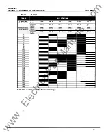
5. 12. 10 Alarm Delay Setpoint
To determine how long a condition exists before an
alarm activates, you must set the alarm delay. Both
alarms have an independent alarm delay; however, the
delay setting is common to all six alarm conditions.
The alarm delay times how long the condition is
continuously above any active alarm threshold, and
activates the alarm when the preset time is exceeded.
28
TD1 7548A
The timer resets when the condition is below the alarm
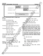
threshold. See Table 5.R for setting the alarm delays.
•= OFF
CJ
= ON
Table 5.R Alarm Delay Settings
5. 12. 1 1 Alarm Reset Delay Setpoint
For the reset delay, the IQ DP-4000 determines how
long the condition must be corrected before the
corresponding alarm is reset. Both alarms have an
independent reset delay; however, the delay setting is
common to all six alarm conditions.
The reset delay measures how long the condition is
continuously within the reset threshold, and clears the
alarm only when the preset delay time is exceeded. The
delay timer resets to zero when the condition is no
longer within the alarm reset threshold. See Table 5.S to
set the alarm reset delays.
•= OFF
CJ
= ON
Table 5.S Reset Delay Settings
5. 12. 12 Overvoltage Detection Level Alarm Setpoint
This setpoint activates the alarm on an overvoltage
condition (see Section 5.1 2.3). You must determine the
overvoltage detection level. The overvoltage detection
level is selected as a larger percentage of the nominal
AC line voltage (see Section 5.5).
www
. ElectricalPartManuals
. com


