Eaton Cutler-Hammer IQ DP-4000 Скачать руководство пользователя страница 8

IQ  DP-4000 
SECTION 2 - HARDWARE  DESCRIPTION 

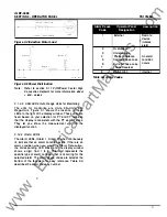
9.  The  discrete  input can  be  configured  to  be either a 

reset  input  or  a  sync  pulse  input.  The  input  is 
activated  by a contact closure across terminal block 

contacts  1  and 2. See Section 5. 1 5. 1  for configuring 
this input. 

1 0.  Watt-hour  Pulse.  The  Watt-hour  pulse  initiator  is  a 

set of contacts that completes  a circuit  and  sends  a 
pulse signal  to  an  external  pulse  recorder.  You  can 

program  the  amount  of  energy  between  pulses 

using  Setpoint  Switches  (see  Section  5. 1 5.3).  The 
pulse initiator is a KYZ output,  meaning the relay will 

change state for each pulse. 

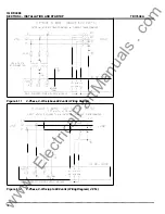
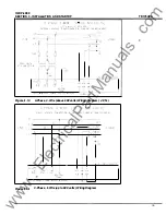
2. 1.3  User-Supplied External Hardware 

The  IQ DP-4000  requires  you  to  wire  at  least 2 ,  and  up 

to  3  current  transformers  into  the  CT  terminal  block 

from  an  external  location  (see  Figures  4.4  - 4. 1 5) .  
These  are  user-supplied  and  must  have  a  5  amp 
secondary.  Potential  transformers  are  required  only for 
voltages  above  600  V  and  are wired  directly to  the  AC 

line connection terminals. 

2. 1.4  Optional Communications  Module 

The  IQ  DP-4000  is  an  I M PACC-(Integrated  Monitoring 

Protection  and  Control  Communications)  compatible 
device.  IMPACC  can  remotely  monitor,  control  and 
program  the  IQ  DP-4000  when  it  is  equipped  with  the 
optional  communications  module.  An  I PONI  is  typically 
mounted on the back of the power module and connects 

to  the  IQ DP-4000  via  the  communications  port  on  the 
lower right side of the rear of the chassis. 

IMPACC  is  a  noise  immune  communications  system 

that  permits communications from  the  IQ  DP-4000 to  a 
master  computer  via  a  high  frequency  carrier  signal 

over  a  shielded  twisted  pair  of  conductors.  The 

conductors  can  extend  up  to  1 0,000  feet  without  using 

repeaters.  The  INCOM  (Industrial  Communications) 
chip 

allows 

communications 

between 

IMPACC 

compatible devices,  and  accounts for the system's  high 
degree of  reliability. 

Functions 

available 

remotely 

communications option are: 

through 

the 

• 

Monitoring  and  trending  of  displayed  values  and 

device status 

• 

Device programming 

• 

Min/Max values 

• 

Cause of alarm 

information 

2. 1.4.1  IMPACC Series 

Ill 

Software 

Series  I l l   Software  provides  the  ability  to  monitor  and 
record  power  distribution  system  data  as  it  occurs. 

TD1 7548A 

Series  I l l   is  a  Microsoft™  Windows-compatible 
application  featuring  user-friendly,  menu-driven  screens 

with  easy  set-up  and  operation.  Additional  features 

include: 

• 

System/device alarm  logging and  reporting 

• 

Gateway  interface  for  connectivity  to 

other 

information networks 

• 

Data trending 

2.1 .4.2  JMPACC Enhanced Graphics 

Enhanced  Graphics  software  provides  the  capability  to 

generate custom animated color graphics.  For example, 
animated  one-line  drawings  of  electrical  power 
distribution  systems,  flow  diagrams  of  processes, 
equipment  elevation  view,  and  other  graphical 
representations can be developed. 

2. 1.4.3  IMPACC Connectivity 

An  I M PACC  network  or  computer  running  Series  I l l  
software can interface with  other networks.  Examples of 

I MPACC connectivity interfaces include: 

• 

PLCs  (Programmable Logic Controllers) 

• 

DCSs  (Distributed Control  Systems) 

• 

BMSs (Building Management Systems) 

• 

PC-based graphical operator interface programs 

2.2  SPECIFICATIONS 

This section covers the following specifications: 

• 

General Specifications (Table 2.A) 

• 

Protection  Function  Specifications  (Table 2.B) 

• 

Metering specifications  (Table 2.C) 

2.2. 1  General Specifications 

The IQ DP-4000 meets the following specifications: 

Function 

Specifications 

Power 
Requirement 

PT  Burden 

(3-Phase 

power 

module)  1 0VA 
PT  Burden 

se  arate  source 

www 

. ElectricalPartManuals 

. com 

Содержание Cutler-Hammer IQ DP-4000

Страница 1: ...or Installation Operation and Maintenance of Cutler Hammer IQ DP 4000 Electrical Distribution System Monitor IteO Cutler Hammer Effective October 1997 TD 17548A w w w E l e c t r i c a l P a r t M a n...

Страница 2: ...oduction 2 Hardware Description 3 Operator Panel 4 Installation and Startup 5 Programming the IQ DP 4000 6 Maintenance and Troubleshooting Maintenance If you are replacing an IQ Data Plus II with an I...

Страница 3: ...ng power facilities or claims against the purchaser or user by its customers resulting from the use of the information and descriptions contained herein vi TD1 7548A LIABILITY INFORMATION Safety Preca...

Страница 4: ...3 Phase AC lines Transformer feeder circuits Branch circuits Motor starters 3 Phase electrical loads The device will automatically display the appropriate unit value in Units Kilo Units or Mega Units...

Страница 5: ...INTS MUST CORRESPOND WITH AN EXISTING VALID DPII SETPOINT SEE TO 17271 FOR DATA PLUS II SETTINGS THE WIRING IS IDENTICAL WITH THE EXCEPTION OF THE SEPARATE SOURCE POWER MODULE TERMINALS NOTE THAT NO J...

Страница 6: ...chassis Figure 2 1 shows the rear of the chassis and includes 1 The 3 Phase AC line connections to the voltage terminal block at the bottom of the power module 2 The current transformer terminal block...

Страница 7: ...the cover in place see Figures 2 2 and 2 3 4 TD17548A 7 A fuse external to the power module is located on the rear right of the chassis This fuse is a 1 4 amp fuse to protect the 24V on Terminal Bloc...

Страница 8: ...hout using repeaters The INCOM Industrial Communications chip allows communications between IMPACC compatible devices and accounts for the system s high degree of reliability Functions available remot...

Страница 9: ...voltages exceeds the percentage of nominal line voltage by a factor of 5 1 0 1 5 20 25 30 35 or 40 The Setpoint Switch position determines the factor Phase Reversal A phase reversal is detected if a...

Страница 10: ...1 digit VA 1 0 6 1 0 6 1 1 digit Watt hours 1 0 6 1 0 6 1 1 digit Var hours 1 0 6 1 0 6 1 1 digit VA hours 1 0 6 1 0 6 1 1 digit Power Factor I 1 I 1 Frequency 1 0 1 Hz 1 0 1 Hz THO Through 3 1 st Har...

Страница 11: ...pushbuttons step through the items that the IQ DP 4000 monitors If you press the Up and the Down buttons 8 TD1 7548A at the same time the INCOM network address for your unit appears in the Display Win...

Страница 12: ...and the THO LED to blink When the display is restored the Maximum THO values have been reset Reset and Demand Holding the Reset and the Demand pushbuttons simultaneously for three to four seconds will...

Страница 13: ...s open Power flow is in Quadrant 4 The Power Factor and Vars will be negative and the respective LED s will blink 2 Breakers A and C are closed and B is open Power flow for Breaker A and C is in Quadr...

Страница 14: ...he measurement unit for the displayed function 3 1 3 4 Alarm LED s The Alarm LEOs Alarm 1 Alarm 2 when continuously lit indicate that an alarm condition exists If there is an alarm condition when you...

Страница 15: ...e IQ DP 4000 chassis allow mounting in the desired location Figure 4 1 shows height and width dimensions while Figure 4 2 shows depth dimensions When you make the cutout and place the holes for the mo...

Страница 16: ...at The location allows for a cable connection between the IQ DP 4000 chassis and the TD1 7548A power module using either the 36 in 91 4 em or the 45 in 1 14 25 em Extension Cable Option The separated...

Страница 17: ...or 120 240 VAC or 30 VDC 4 The wires connecting to the IQ DP 4000 must not be larger than AWG No 1 4 Larger wires will not connect properly with the various terminal blocks 5 Keep the wiring between t...

Страница 18: ...SOURCE POWER SUPPLY MOD0 _E 6 H1C H1B HIA Figure 4 5 3 Phase 3 Wire above 600 volts Wiring Diagram Separate Source LINE 100 350 VDC 96 264 VAC CONTROL POWER 3 ASE 3 WIRE UP TO 600 VO LTS 2 CT s WITH I...

Страница 19: ...B H2A Figure 4 7 3 Phase 3 Wire above 600 volts Wiring Diagram Separate Source 2 CTs LINE 100 350 VDC 96 264 VAC CONTROL_ POWER 3 PHASE 4 WIRE UP TO 600 VOLIS DIRECT VOUAGE CONNECTION EXTERNAL CURREW...

Страница 20: ...PLY MODULE 6 HIC riB lA Figure 4 9 3 Phase 4 Wire above 600 volts Wiring Diagram Separate Source 3 PHASE 3 WIRE UP TO 600 VOLTS DIRC CT VOLTAGE CON ECTION EXERNAL CURRENT TRANSFORMERS c 3CT LINE L3 Y1...

Страница 21: ...LE 0 6 H1C H1B H1A ci2C H2B I Figure4 11 3 Phase 3 Wire above 600 volts Wiring Diagram L 3 LINE L2 L1 3 PHASE 3 WiRE UP TO 600 VOLTS 2 CT s WITH IQ DP 4000 DIRECT VOLTAGE CONNECTION EXTERNAL CURRENT T...

Страница 22: ...POWERED POWER SUPPLY MODULE 6 6 fll C c l 8 HIA r 2C H28 H2A r I r Figure4 1 3 3 Phase 3 Wire above 600 volts Wiring Diagram 2 CTs 3 PHASE 4 WIRE ruo f 600 VOLTS I v DiRECT VOLTAGE CONNECTION EXTERNAL...

Страница 23: ...ECHANICAL EQUIPMENT FAILURE TO OBSERVE THIS CAUTION CAN RESULT IN SERIOUS INJURY OR EVEN DEATH 20 4 5 1 During Initial Power Application To apply AC power to the IQ DP 4000 for the first time 1 Verify...

Страница 24: ...switch to 0 SW1 Configuration Frequency Nominal AC Line Voltage Transform Transformer er Ratio Primary SW2 Voltage SW3 Current Primary SW4 Power Power Current Demand Phase Sequence Demand Time Interva...

Страница 25: ...5 1 5 3 1 Load Shed Range 5 1 5 3 2 Load Shed Parameter 5 1 5 3 3 Pulse Initiator Settings Rate Selection 5 1 5 3 4 Table5 0 Optional V O Functions 5 2 SETTING SETPOINT SWITCHES To program the IQ DP 4...

Страница 26: ...ndicating they are in the on position 9 Press and hold the Save button until the tenth LED lights The setting for Select Switch 3 is now TD1 7548A permanently stored in the device s long term memory 1...

Страница 27: ...PHASE SEQUENCE SETPOINT The IQ DP 4000 can be programmed to correspond to either a nominal ABC or CBA sequence by a single switch SW4 No 1 A power system with an ABC sequence has phase A leading phas...

Страница 28: ...electing the power demand interval OFF Q ON Not Applicable Table5 G Power Demand Intervals for Watts Vars and V A TD1 7548A 5 9 3 Current Demand Time Interval Switch SW4 Nos 6 7 and 8 determine the ti...

Страница 29: ...y and de energizes during a loss of AC control power You must select one of these two modes for each alarm Your choice depends on the desired effect of an AC power loss on an application as described...

Страница 30: ...rm if the metered voltage is below the threshold for a time greater than the alarm delay on any phase see Section 5 12 1 0 See Table 5 L for setting this option TD1 7548A Alarm 1 Alarm 2 Position SW6...

Страница 31: ...r activate the alarm Table 5 Q Enable Disable Alarm 5 12 10 Alarm Delay Setpoint To determine how long a condition exists before an alarm activates you must set the alarm delay Both alarms have an ind...

Страница 32: ...se unbalance detection level A voltage phase unbalance is calculated by taking the maximum voltage deviation between any two phases TD1 7548A and comparing that voltage to a percentage of the nominal...

Страница 33: ...ervoltage detection level see Section 5 1 2 1 2 Figure 5 1 illustrates the overvoltage set and reset levels The reset voltage is a percentage of the difference 0 to 1 00 between the nominal voltage an...

Страница 34: ...e overvoltage alarm will occur at 480V X 1 1 0 528 V Overvoltage Detection Level Volts Reset Threshold 50 Nominal Line to Line Voltage Volts 504V 528V RST x 528V 480V 504V 528V RST x 48V RST x 48V 528...

Страница 35: ...Line to Line Voltage Volts Reset Threshold 50 Undervoltage Detection Level Volts 420V 360V RST x 1 20V RST x 1 20V 420V 360V 60V RST 60V I 1 20V 0 50 In this case set the reset threshold to 50 5 12 15...

Страница 36: ...ts when all 3 phases are within 31V 31 V x 75 8V of each other Example 2 A system has the following settings Nominal AC Line Voltage 480 V Voltage Phase Unbalance Detection Level 25 Determine the rese...

Страница 37: ...start of a new demand window The sync window time can be variable or fixed determined by setting the sync pulse setpoint see 5 1 5 3 34 TD1 7548A If the discrete input is set up as a reset input a dr...

Страница 38: ...n the Load Shed range is exceeded the relay activates This relay remains active until the value of the selected parameter drops below the Restore Load range The nominal system voltage is explained in...

Страница 39: ...ed Select SWE SWE SWE of nominal Switch No 1 No 2 No 3 SWE No 4 Res t ore Load SWE SWE SWE SWE o f nominal No 5 No 6 No No B Table 5 Y Load Shed and Restore Load Settings continued on next page TD1 75...

Страница 40: ...es I Switch Settings Load Shed Select SWE SWE SWE SWE SWD SWD of nominal Switch r No 1 No 2 No 3 No 4 No 5 No 6 S WE SWE S WE SWE SWD SWD No 5 No 6 No 7 No 8 No 7 No 8 Table 5 Y Load Shed and Restore...

Страница 41: ...selected the relay changes state every time 50 Watt hours accumulate The energy per pulse corresponds to the energy in units at the secondary winding of the PTs and CTs Therefore you must consider the...

Страница 42: ...at the main disconnect or isolation switch of the power supply If the switch is not located in view of the IQ DP 4000 lock it out to guard against other personnel accidentally turning on the switch 2...

Страница 43: ...4000 is detecting an internal indicating an internal malfunction malfunction One or more voltage phases read Blown or loose fuse s incorrectly Incorrect PT ratio Current readings are not accurate or r...

Страница 44: ...e correct voltage level Check that the fuses are sitting correctly in their clips Replace the unit Determine why the trip was initiated from the external device through the Communications Port Isolate...

Страница 45: ...is external or internal to the unit For assistance with this determination please contact Advanced Product Support APSC at 1 800 809 2772 If a problem is identified as internal return the unit to the...

Страница 46: ...P 4000 APPENDIX A PT RATIO AND CT PRIMARY SETPOINT VALUES OFF ON PT Switch Settings Values PT Ratio SW1 SW2 SW2 SW2 SW2 TO 1 7548A SW2 SW2 S W2 SW2 43 w w w E l e c t r i c a l P a r t M a n u a l s c...

Страница 47: ...ETPOINT VALUES 44 OFF ON PT Switch Settings Values P T Select S W1 Ratio Swit ch PT 1 Setpoint No 7 Swit ch SW2 No 1 SW 2 SW2 SW2 No 2 No 3 No 4 TD1 7548A SW2 S W 2 SW2 SW2 No 5 No 6 No 7 No 8 w w w E...

Страница 48: ...Y SETPOINT VALUES OFF ON PT Switch Settings Values P T Ratio PT 1 Select SW1 Switch Setpoint No 7 Switch SW2 1 SW2 SW2 SW2 No 2 No 3 No 4 TO 1 7548A SW2 S W 2 SW2 SW 2 No 5 No 6 No 7 No 8 45 w w w E l...

Страница 49: ...SETPOINT VALUES 46 OFF ON PT Switch Settings Values PT Select SW1 R atio Swit ch PT 1 Setpoint No 7 Swit ch SW2 No 1 SW 2 SW2 SW2 2 No 3 No 4 TD1 7548A SW2 SW2 SW 2 SW 2 No 5 No 6 No 7 No 8 w w w E l...

Страница 50: ...ETPOINT VALUES OFF ON PT Switch Settings Values P T Select SW1 SW2 Ratio Switch PT 1 Setpoint No 7 No 1 Swit ch SW2 No 2 S W2 S W2 No 3 No 4 TO 1 7548A S W2 SW2 S W2 S W2 No 5 No 6 No 7 No 8 47 w w w...

Страница 51: ...PRIMARY SETPOINT VALUES I 48 OFF ON PT Switch Settings Values PT Ratio PT 1 Select Switch SW1 SW2 No 7 No 1 SW2 S W2 S W 2 No 2 No 3 No 4 TD1 7548A SW 2 S W2 SW2 SW2 No 5 No 6 No 7 8 w w w E l e c t...

Страница 52: ...SETPOINT VALUES OFF ON PT Switch Settings Values PT Ratio PT 1 Select SW1 Switch Setpoint No 7 Switch SW2 No 1 SW2 SW2 S W2 No 2 No 3 No 4 TD 17548A SW 2 SW 2 S W2 S W2 No 5 No 6 No 7 No 8 49 w w w E...

Страница 53: ...PRIMARY SETPOINT VALUES OFF ON PT Switch Settings 50 Values PT Ratio PT 1 Select Switch SW1 SW 2 No 7 No 1 SW2 S W2 S W 2 No 2 3 No 4 TD1 7548A SW2 SW2 S W 2 SW2 No 5 No 6 No 7 No 8 w w w E l e c t r...

Страница 54: ...AND CT PRIMARY SETPOINT VALUES OFF ON PT Switch Settings Values Select Switch SW1 No 7 SW2 No 1 SW2 S W2 SW 2 No 2 No 3 No 4 TD 1 7548A SW 2 SW2 S W2 S W2 No 5 No 6 No 7 No 8 51 w w w E l e c t r i c...

Страница 55: ...AND CT PRIMARY SETPOINT VALUES 52 OFF ON PT Switch Settings Values Select Switch SW1 SW2 No 7 No 1 S W 2 SW 2 SW2 No 2 No 3 No 4 TD1 7548A SW2 S W 2 SW 2 SW2 No 5 No 6 No 7 No 8 w w w E l e c t r i c...

Страница 56: ...RIMARY SETPOINT VALUES OFF ON PT Switch Settings Values PT Ratio PT 1 Se lect Switch SW1 SW 2 No 7 No 1 SW2 S W2 SW 2 No 2 No 3 No 4 TD 1 7548A SW 2 S W2 S W2 SW2 No 5 No 6 No 7 No 8 53 w w w E l e c...

Страница 57: ...RIMARY SETPOINT VALUES OFF ON PT Switch Settings 54 Values PT Ratio PT 1 Select Swit ch SW1 S W 2 No 7 No 1 SW2 SW 2 S W2 No 2 No 3 No 4 TD1 7548A S W2 SW2 SW 2 SW2 No 5 No 6 No 7 No 8 w w w E l e c t...

Страница 58: ...SETPOINT VALUES OFF ON PT Switch Settings Values PT Ratio PT 1 Select SW1 Swit ch Setpoint No 7 Switch S W 2 No 1 SW 2 SW2 S W2 No 2 No 3 No 4 TO 17548A SW2 SW 2 SW2 SW2 No 5 No 6 No 7 No 8 55 w w w E...

Страница 59: ...TPOINT VALUES OFF ON PT Switch Settings 56 Values PT Ratio PT 1 Select SW1 Sw itch Setpoint No 7 Sw itch SW 2 No 1 S W2 S W2 SW 2 No 2 No 3 No 4 TD1 7548A SW2 SW2 S W 2 S W2 No 5 No 6 No 7 No 8 w w w...

Страница 60: ...Y SETPOINT VALUES OFF ON CT Switch Settings Values CT Select SW1 SW3 SW3 SW3 SW3 TD 17548A SW3 SW3 SW3 SW3 Primary Switch CT 5 Setpoint No 8 No 1 No 2 No 3 No 4 No 5 No 6 No 7 No 8 Switch 57 w w w E l...

Страница 61: ...AND CT PRIMARY SETPOINT VALUES 58 OFF ON CT Switch Settings Values CT Select SW1 Switch No 8 SW3 No 1 SW3 SW3 SW3 No 2 No 3 No 4 TD1 7548A SW3 SW3 SW3 SW3 No 5 No 6 No 7 No 8 w w w E l e c t r i c a...

Страница 62: ...SETPOINT VALUES OFF ON CT Switch Settings Values CT Select SW1 SW3 SW3 SW3 SW3 TD 1 7548A SW3 SW3 SW3 SW3 Primary Switch CT 5 Setpoint No 8 No 1 No 2 No 3 No 4 No 5 No 6 No 7 No 8 Switch 59 w w w E l...

Страница 63: ...Y SETPOINT VALUES OFF ON CT Switch Settings Values CT Select SW1 SW3 SW3 SW3 SW3 TD1 7548A SW3 SW3 SW3 SW3 Primary Switch CT S Setpoint No 8 No 1 No 2 No 3 No 4 No 5 No 6 No 7 No 8 Switch 60 w w w E l...

Страница 64: ...Y SETPOINT VALUES OFF ON CT Switch Settings Values CT Select SW1 SW3 SW3 SW3 SW3 TO 17548A SW3 SW3 SW3 SW3 Primary Switch CT S Setpoint No 8 No 1 No 2 No 3 No 4 No 5 No 6 No 7 No 8 Switch 61 w w w E l...

Страница 65: ...SETPOINT VALUES OFF ON CT Switch Settings Values CT Select SW1 SW3 SW3 SW3 SW3 TD17548A SW3 SW3 SW3 SW3 Primary Switch r CT 5 Setpoint No 8 No 1 No 2 No 3 No 4 No 5 No 6 No 7 No 8 Switch 62 w w w E l...

Страница 66: ...alues CT Select SW1 SW3 SW3 SW3 SW3 TD 1 7548A SW3 SW3 SW3 SW3 Primary Switch r CT 5 Setpoint No 8 No 1 No 2 No 3 No 4 No 5 No 6 No 7 No 8 Switch These CT Primary values are repeated from previous pag...

Страница 67: ...Values CT Select SW1 SW3 SW3 SW3 SW3 TD17548A SW3 SW3 SW3 SW3 Primary Switch r CT S Setpoint No 8 No 1 No 2 No 3 No 4 No 5 No 6 No 7 No 8 Switch These CT Primary values are repeated from previous page...

Страница 68: ...SETPOINT VALUES OFF ON CT Switch Settings Values CT Select SW1 SW3 SW3 SW3 SW3 TO 1 7548A SW3 SW3 SW3 SW3 Primary Switch 4 CT S Setpoint No 8 No 1 No 2 No 3 No 4 No 5 No 6 No 7 No 8 Switch 65 w w w E...

Страница 69: ...Y SETPOINT VALUES OFF ON CT Switch Settings Values CT Select SW1 SW3 SW3 SW3 SW3 TD1 7548A SW3 SW3 SW3 SW3 Primary Switch 66 CT 5 Setpoint No 8 Switch No 1 No 2 No 3 No 4 No 5 No 6 No 7 No 8 w w w E l...

Страница 70: ...Y SETPOINT VALUES OFF ON CT Switch Settings Values CT Select SW1 SW3 SW3 SW3 SW3 TD 17548A SW3 SW3 SW3 SW3 Primary Switch CT S Setpoint No 8 No 1 No 2 No 3 No 4 No 5 No 6 No 7 No 8 Switch 67 w w w E l...

Страница 71: ...Y SETPOINT VALUES OFF ON CT Switch Settings Values CT Select SW1 SW3 SW3 SW3 SW3 TD1 7548A SW3 SW3 SW3 SW3 Primary Switch CT 5 Setpoint No 8 No 1 No 2 No 3 No 4 No 5 No 6 No 7 No 8 Switch 68 w w w E l...

Страница 72: ...SETPOINT VALUES OFF ON CT Switch Settings Values CT Select SW1 SW3 SW3 SW3 SW3 TO 1 7548A SW3 SW3 SW3 SW3 Primary Switch CT 5 Setpoint No 8 No 1 No 2 No 3 No 4 No 5 No 6 No 7 No 8 Switch 69 w w w E l...

Страница 73: ...Y SETPOINT VALUES OFF ON CT Switch Settings Values CT Select SW1 SW3 SW3 SW3 SW3 TD1 7548A SW3 SW3 SW3 SW3 Primary Switch CT S Setpoint No 8 No 1 No 2 No 3 No 4 No 5 No 6 No 7 No 8 Switch 70 w w w E l...

Страница 74: ...for your setpoint switches record them in this table Remove and store this table in several locations and keep it up to date when you change settings No 1 No 2 No 3 No 4 No 5 No 6 No 7 No 8 SW1 SW2 S...

Страница 75: ...nt Select Switch Use the following pages to record your settings for each setpoint They are organized by General System Alarm 1 Alarm 2 and Optional 1 0 Setpoints This page contains the settings for S...

Страница 76: ...etpoint 1 1 1 1 1 1 Display 2 2 2 2 2 2 3 3 3 3 3 3 4 4 4 4 4 4 5 5 5 5 5 5 6 6 6 6 6 6 7 7 7 7 7 7 8 8 8 8 8 8 Setpoint 1 1 1 1 1 1 Switch 2 2 2 2 2 2 3 3 3 3 3 3 4 4 4 4 4 4 5 5 5 5 5 5 6 6 6 6 6 6...

Страница 77: ...OFF r J ON OFF 50 Hz ON 60 Hz Not Applicable Not Applicable Nominal AC Line Voltage OFF r J ON See Table 5 F 74 Not Applicable Voltage Transformer Ratio OFF r J ON See Appendix A Not Applicable Curre...

Страница 78: ...nd Time Interval OFF l l ON 4 See Table S H Not Applicable TD 17548A Reset Energy from Faceplate OFF l l ON 5 OFF Disabled ON Enabled Energy Resolution OFF l l ON ON Mega Units Not Applicable Not Appl...

Страница 79: ...B SETPOINT RECORD SHEETS INCOM Programmable OFF 0 ON c OFF Disabled ON Enabled 76 Not Applicable DP 4000 DP 2 Mode OFF 0 ON ON DP 4000 Mode TD1 7548A Not Applicable w w w E l e c t r i c a l P a r t...

Страница 80: ...Latched Not Applicable Alarm 1 Activate on Overvoltage OFF D ON OFF Disabled ON Enabled Not Applicable Alarm 1 Activate on Undervoltage OFF D ON Not Applicable ON Enabled Alarm 1 Activate on Voltage P...

Страница 81: ...ss OFF D ON ON Enabled Alarm 1 Enable Disable OFF D ON 8 OFF Disabled ON Enabled 78 Not Applicable Not Applicable Alarm 1 Trip Delay OFF D ON 8 See Table S R Alarm 1 Reset Delay OFF D ON 8 See Table S...

Страница 82: ...oltage Detection Level Alarm 1 Reset Threshold OFF CJ ON Not Applicable OFF CJ ON Not Applicable See Table S U See Table S W Alarm 1 Voltage Phase Unbalance Detection Level OFF CJ ON Not Applicable 9...

Страница 83: ...N Not Applicable ON Latched Alarm 2 Activate on Overvoltage OFF CJ ON Not Applicable ON Enabled 80 Alarm 2 Activate on Undervoltage OFF CJ ON OFF Disabled ON Enabled Not Applicable Alarm 2 Activate on...

Страница 84: ...on Current Phase Loss OFF D ON 7 OFF Disabled ON Enabled Alarm 2 Enable Disable A OFF Disabled ON Enabled Not Applicable Alarm 2 Trip Delay OFF D ON A See Table S R Alarm 2 Reset Delay OFF D ON See Ta...

Страница 85: ...2 Undervoltage Detection Level Alarm 2 Reset Threshold OFF 0 ON Not Applicable OFF 0 ON Not Applicable 8 See Table 5 U Alarm 2 Voltage Phase Unbalance Detection Level OFF 0 ON Not Applicable See Table...

Страница 86: ...J ON Not Applicable ON Demand window is timed internally Pulse Initiator Load Shed OFF D ON Not Applicable D OFF Relay acts as pulse initiator ON Relay acts as load shed Pulse Initiator Parameter OFF...

Страница 87: ...NDIX B SETPOINT RECORD SHEETS TD1 7548A Load Shed Parameter Pulse Initiator Rate OFF D ON Not Applicable OFF D ON Not Applicable See Table 5 Z See Table S AA 84 w w w E l e c t r i c a l P a r t M a n...

Отзывы: