background image

U  Page 57

Digital controller RK 4004

5.3 "Three position controller"

upgrade

No.

Name

 Default

Min.

Max.

 Unit

Description

.1.3.

puls range ±

2.0

0.0

2000.0

mm

Switching threshold for transition
Stop at pulse output

.1.4.

slow range ±

4.0

0.0

2000.0

mm

Switching threshold for transition
Pulse output to permanent signal

.1.5.

fast range ±

6.0

0.0

2000.0

mm

Switching threshold for transition
Permanent signal to fast signal

.1.6.

hysteresis

1.0

0.0

2000.0

mm

Hysteresis of the individual switching thresholds

.1.7.

pulse ON-time

1.0

0.0

10.0

sec

Switch-on time of pulse signal

.1.8.

pulse OFF-time

1.0

0.0

10.0

sec

Switch-off time of pulse signal

.1.9.

jog with fast

0

0

1

Jog mode with fast signal

.2.0.

dig. I/O adress

0

0

7.F

hex

Address of digit. output card for the positioning  signals

.2.1. •

act. control out

Display of the current positioning signal

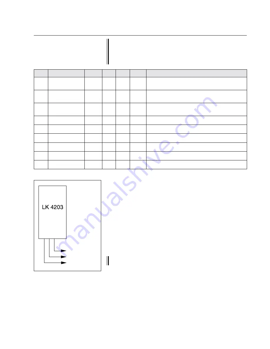
Output:
"Right"
"Left"
"Fast"

For control card applications as a three position controller the va-
lue 32 must be entered in parameter "..3. start service" during
control card commissioning. This loads the three position control-
ler parameter record. The three position controller parameters that
differ from the norm are described below.

.1.3. puls range ± 

(switching threshold 1)

.1.4. slow range ± 

(switching threshold 2)

.1.5. fast range ± 

(switching threshold 3)

The three position controller software features 3 switching thresholds.

Switching threshold 1pulsed "Right" or "Left" output

Switching threshold 2 "Right" or "Left" output duration

Switching threshold 3 "Fast" output duration

The "Fast" output is switched to threshold 2.

The switching thresholds should be entered in the appropriate para-
meters. The entered value corresponds to the unit mm .

If a switching point is not required, the value "0" must be set in the
appropriate parameter.

Содержание RK 4004

Страница 1: ...overview 7 3 Assembly 7 4 Installation 8 4 1 Terminal assignments X 1 to X 21 9 4 2 Setup operation 10 5 Parameters 13 5 1 Parameter list 13 5 2 Explanation of parameters 20 5 3 Three position control...

Страница 2: ...bus for the position controlling of running webs and following up of tools Operation is via a command device with text display and or a digital input output card The controller card consists of the f...

Страница 3: ...iting is only effective in automatic mode and may be acti vated on controller card RK 4 or via an interface Web offset A web offset may be set in automatic mode A web offset means that the set positio...

Страница 4: ...S push roller SVS and VSS positioning and follow up controller 1 4 Control structure with constant controlling for proportional actuators Control structure legend 1 Operating mode 2 Actuator position...

Страница 5: ...speed in search for edge mode 15 Variable current controller 16 Current controller 17 Variable actuating speed during positioning 18 Oscillation generator In a control structure for a support beam a...

Страница 6: ...ent controller 1 6 Control structure with con stant controlling for inte gral actuators In the case of a control structure for integral actuators the web actual position value is compared to the requi...

Страница 7: ...overview of the most common digital controllers The individual digital controllers DC are listed in the ver tical column The crosses mark the components belonging to them AK LK etc 3 Assembly Control...

Страница 8: ...0 End switch X 21 Supply voltage for further E L modules X 1 Operating volta ge The wiring diagram indicates which connectors are assigned The guider lock is intended for on site requirements where th...

Страница 9: ...only 3 X 0 V 4 X Sensor range limit X 4 1 X Guider lock 2 X 0 V potential 0 V for controller lock 3 X 24 V DC reference switch 4 X Reference switch signal 5 X 0 V reference switch 6 X 24 V DC 7 X Act...

Страница 10: ...004 must be checked and changed as necessary Press both keys decrease value and increase value at the same time The group number is indicated via the decrease value key and the device number via the i...

Страница 11: ...coder fault incremental encoder motor fault 6 encoder invers incremental encoder motor inverted 7 sensor R fault no message from right sensor 8 sensor L fault no message from left sensor 9 gearconstan...

Страница 12: ...parameters press and hold down the setup key and select the required para meter via the increase value key Release the set up key again and enter the required parameter value via the increase or decr...

Страница 13: ...ttings 0 no function 1 perform customer settings 2 perform internal default setting 3 start service 0 0 199 Starting a function 0 no function 1 reset controller 2 save parameter 10 actuator initialisa...

Страница 14: ...ity auto 20 0 1000 mm s Max positioning velocity speed in automatic mode 1 7 velocity pos 50 0 1000 mm s Positioning velocity speed in positioning mode 1 8 velocity jog 10 1 1000 mm s Positioning velo...

Страница 15: ...on ratio from rotational to linear movement 3 7 mech gearfactor 1 00 0 10 5 00 Mechanical ratio 3 8 reserved 38 not assigned at present 3 9 reserved 39 not assigned at present 4 0 pos controller Param...

Страница 16: ...r 6 3 current_I 0 4 0 0 50 0 I component for current controller 6 4 set current Set motor current display 6 5 reserved 65 not assigned at present 6 6 reserved 66 not assigned at present 6 7 reserved 6...

Страница 17: ...Use of input X20 2 8 6 usage input X 3 2 10 10 Use of input X3 2 8 7 reserved 87 not assigned at present 8 8 reserved 88 not assigned at present 8 9 reserved 89 not assigned at present 9 0 reserved 90...

Страница 18: ...config 0000 0000 FFFF Operator key use all sensors 0x0001 Auto take photo 0x0002 force support free 0x0004 Cente supp free 0x0008 unused sup free 0x0010 no edge sens free 0x0020 sens sel direct 0x0040...

Страница 19: ...positioning path 16 the positioning path depends on an external CAN signal 32 the positioning path depends on the web speed 1 1 9 adaptive ratio 0 0 409 6 Display of the current control loop amplific...

Страница 20: ...twork In order for a specific device to be addressed in the control loop the device number must be set in parameter 0 edit device and the group number in parameter 1 edit group The device and group nu...

Страница 21: ...with specification of motor and gear data In this initialisation run by first entering the motor and gear data parameter 3 4 3 5 3 6 and 3 7 the maximum positioning path is established and entered in...

Страница 22: ...gs are stored in a backup list If necessary all customer specific settings may be reloaded using parameter 2 reset settings 98 Delete error memory This command should only be used by E L service perso...

Страница 23: ...of fixed sensors or a single motor support beam with two positioning carriages the web offset is limited to 75 of the sensor measuring range For the remaining applications with sup port beams and cam...

Страница 24: ...eriod Oscillation time tc n sections web length s s s web length per oscillation period fc max Vmax s x 60 fc max maximum oscillation frequency 1 s Vmax maximum web speed m min s web length per oscill...

Страница 25: ...zero pass In the case of path dependent oscillation the corresponding pulses must be supplied up to the zero pass For path dependent oscillation the digital input X 3 2 must be pro grammed to web spee...

Страница 26: ...tivity the guider will overshoot as well In the case of too little amplification the control loop will be too slow Optimum amplification may be determined with a characteristic curve tracer In practic...

Страница 27: ...ositioning velocity is 15 mm s for a proportional range of 2 mm and 8 0 mm s for a pro portional range of 3 5 mm The values may also be calculated arithmetically Amplification G parameter 1 6 Paramete...

Страница 28: ...portional range Correction positioning path Control deviation 18 mm 10 5 mm By reducing the proportional range the characteristic curve see fig becomes steeper The steeper the characteristic curve the...

Страница 29: ...se two parameters may be used to determine a range in which given a deviation from the set position the correction velocity of the actua tor is reduced in the case of proportional guiders Given a web...

Страница 30: ...Positioning velocity 1 6 velocity auto 15 mm s 20 mm s Proportional range 1 3 prop range 2 0 Control deviation of 1 5 mm Set position Sensor measuring range center established correction velocity dep...

Страница 31: ...15 2 7 5 1 s G 20 2 10 0 1 s VK 1 5 mm 7 5 1 s VK 1 5 mm 10 0 1 s VK 11 25 mm s VK 15 0 mm s If the positioning velocity is too high the web guider will begin to oscil late The maximum positioning vel...

Страница 32: ...selected in pa rameter 9 7 2 0 derated velocity Not assigned at present 2 1 reseved 21 Not assigned at present 2 2 defect range If the set value is exceeded the positioning velocity will be reduced t...

Страница 33: ...tion range is shortened at the factory by approx 2 mm In the case of on site mounting of the DC actuator drive the position range limit must be set by the customer Especially in the case of large move...

Страница 34: ...9 Not assigned at present 3 0 reference offset In this parameter the distance between the reference switch switching point and the center of the DC actuator drive is set To calibrate the internal posi...

Страница 35: ...he actuator neutral positi on is possible at once 3 2 system offset If the DC actuator is located in the center of its positioning range the actual position value 0 will be transmitted via the CAN bus...

Страница 36: ...ion and DC actua tor drive securing point Equally measure distance S 2 between the center of rotation and the outfeed point These two values are set in relation to one another and the value calculated...

Страница 37: ...values parameter 1 3 und 4 5 The DC actuator drive covers the first 10 mm at maximum positioning velocity as these values are outwith the grey range Once the 10 mm are passed only 5 mm remain These 5...

Страница 38: ...rop stroke In the case of integral actuators the correction path is set in relation to the set proportional range parameter 1 3 prop range This parameter has no function for proportional actuators The...

Страница 39: ...arithmetically Amplification G parameter 4 5 parameter 1 3 Correction path control deviation amplification G Example 1 Example 2 G 15 2 7 5 G 20 2 10 0 VK 1 5 mm 7 5 VK 1 5 mm 10 0 VK 11 25 mm VK 15 0...

Страница 40: ...tuator manually moved to the re quired set position The offset is calculated and saved via the setup and automatic key combination 4 7 speed controller Parameter block for setting the speed controller...

Страница 41: ...out ramp function 5 3 I PWM The actual I PWM value pulse width modulated is displayed The display is only of significance for internal tests 5 4 reserved 54 Not assigned at present 5 5 current control...

Страница 42: ...actual permissi ble motor cur rent If the motor current input is less than the nominal motor current the permissible motor current will be increased within the set time 5 9 term timeconst to the inter...

Страница 43: ...7 Not assigned at present 6 8 diagnostics Parameter block for displaying the system status 6 9 system error The following error messages are possible 1 supply voltage under 20 V DC 2 supply voltage ov...

Страница 44: ...rature of the controller card case is displayed here 7 5 temp case max The controller card stores the highest measured temperature of the heat sink This stored temperature is displayed 7 6 reserved 76...

Страница 45: ...he motor direction of rotation is blocked Which direction of rotation is inhi bited is only determined in conjunction with the reference switch see example 1 5 Speed lock at signal 1 the positive moto...

Страница 46: ...ve motor direction of rotation is stopped Input X 4 7 is assigned the value 5 At signal 0 the positive motor di rection of rotation is stopped If the circuit is set up with make contacts value 5 or 6...

Страница 47: ...reversing contactor 9 3 control mode In the case of web center guiding systems with motor driven sensor following up hybrid value 1 must be set Proportional actuator Pivoting frame Steering roller Tur...

Страница 48: ...or or via the command device 1 Device number 1 is automatically assigned to the sensor at ter minal X5 and device number 2 to the sensor at terminal X6 The sensor device group is identical with the co...

Страница 49: ...to the stored center position If this function is not activated the actuator will only be blocked in the event of an invalid sensor signal MCP active 0100h Activation of the MCP MasterControleProcesso...

Страница 50: ...target CAN 0003h Output of the set position value Delta Pos CAN 0004h Output of the position difference I target CAN 0005h Output of the set current value Disable I Loop 0008h If no motor is connected...

Страница 51: ...h In automatic mode non selected sensors mounted on a motor driven positioning carriage are moved to their outer position not active at present Auto SensorFree 0020h If during search for edge mode the...

Страница 52: ...of the guiding criterion when a color line sensor an option is available of switching to what is termed an emergency sensor Emergency guiding is activated in parameter 9 9 operatorkey con fig The per...

Страница 53: ...on Up to 4 mo dules e g a command station several logic cards etc may be seri ally connected via this serial bus The addresses of the serial devices are entered automatically in ascending order beginn...

Страница 54: ...g on the web speed The two vertexes for the characteristic curve are determined via the following parameters Depending on the current web speed a per cent factor is produced on the basis of the charac...

Страница 55: ...is available for adapting the web guider control loop to changing process variables e g web speed Which guider setting is to be influenced by which process variable must be set with one of the followi...

Страница 56: ...e off on For E L service personnel only Service mode is started via value 1 Following a reset the value is automatically reset to 0 1 2 7 service mode For E L service personnel only 2 Square wave curr...

Страница 57: ...1 act control out Display of the current positioning signal Output Right Left Fast For control card applications as a three position controller the va lue 32 must be entered in parameter 3 start serv...

Страница 58: ...thresholds or from one switching threshold to 0 1 7 pulse ON time 1 8 pulse OFF time The switch on and off duration may be set separately for switching threshold 1 parameter 1 3 pulse range The switc...

Страница 59: ...8 8 1 5 40 40 2 9 2750 2 0 0 10 2 6 0 4 AG 2671 311967 8 16 1 5 80 25 4 9 3070 2 0 0 10 2 6 0 4 AG 2671 311946 8 28 1 5 80 25 4 9 3070 2 0 0 10 2 6 0 4 AG 2671 311944 8 16 1 5 80 50 4 9 3070 2 0 0 10...

Страница 60: ...9 3070 2 0 0 10 2 6 0 4 AG 4671 311957 8 11 1 5 80 100 4 9 3070 2 0 0 10 2 6 0 4 AG 4671 311961 8 25 14 1 5 80 100 4 9 3070 2 0 0 10 2 6 0 4 AG 4671 311809 8 11 1 5 80 150 4 9 3070 2 0 0 10 2 6 0 4 AG...

Страница 61: ...rminal 22 V PWM PWM pulse width modulated Maximum output current 7 A Protection class IP 00 CAN bus CAN bus level 5 V potential free CAN baud rate 250 KBaud Sound level digital inputs terminal X 4 1 4...

Страница 62: ...Erhardt Leimer GmbH Post box 10 15 40 D 86136 Augsburg Telephone 0821 24 35 0 Telefax 0821 24 35 666...

Отзывы: