Leaders in Pipelin
e Survey Systems
C
C
C
-
-
-
S
S
S
C
C
C
A
A
A
N
N
N
2
2
2
0
0
0
1
1
1
0
0
0
SYSTEM MANUAL Version 6.03i
50
7.4. Signal Range
When connected to a pipeline, the range of the signal applied by the Signal Generator is
dependant on the following criteria:
1. Wrap/Coating
condition
2. Amount of signal applied
For a pipeline with poor coating, the attenuations will be high and therefore the range will
be limited as more of the signal is ‘leaked’ from the pipeline through poor coating. If a low
signal is applied the range is also reduced. It must be noted that a doubling of the
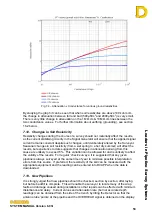
injection current will not result in twice the distance achieved. The following graph shows
the relationship between the maximum range versus attenuation for a given injection
current. The graph assumes that the Signal Generator current is split into two at the
injection point i.e. half the signal goes in one direction and half in the other as is normally
the case. If a survey starts at an insulating joint/flange then the current is doubled as all
the signal heads in the same direction. See section 8.6 for more information.
Range Vs Attenuation
1
10
100
1000
10000
100000
1000000
0
1
2
3
4
5
Attenuation mB/m
Di
st
ance (
ft
)
1000mA
600mA
150mA
Fig 7.3 – Range v Attenuation
7.5. Fault Size
There is no general linear relationship between local attenuation figures and size of
fault/anomaly. These can be affected by local soil resistivity (in particular whether the
pipeline is above or below the local water table) and by the build-up of corrosion deposits
at a fault over time. It is also possible that an apparently small fault at the surface of the
wrap is related to a large area of hidden wrap disbondment and therefore produces a large
local attenuation. It is probable that for any given pipeline, the correlation between fault
size and local attenuation will be closer, but confirmation of this requires more data
collected over an extended period.


