Leaders in Pipelin
e Survey Systems
C
C
C
-
-
-
S
S
S
C
C
C
A
A
A
N
N
N
2
2
2
0
0
0
1
1
1
0
0
0
SYSTEM MANUAL Version 6.03i
57
8.7. Sacrificial Anodes
These are generally used instead of an applied CP current as a means of protecting the
pipeline. They will show up as ‘faults’ on a C-SCAN survey and should be disconnected if
possible because they will severely reduce the available current and thus shorten the
length of pipeline that can be surveyed from one Signal Generator location.
8.8. Pipeline Bends and ‘Tees’
Bends (of radius less than approximately 30ft) and ‘T’ or ‘Y’ junctions in pipelines will often
result in local distortion of the radiated field because of mutual interference between the
signals from adjacent sections. Although discrete coating faults can usually be located in
these areas with a short Close Interval survey, readings taken close to bends and Tees
should not be used to compute attenuation levels over long sections of pipeline. It must be
remembered that bends can be vertical as well as horizontal, especially near river and
road crossings. Reference points should, where possible, be at least 15ft from a bend or
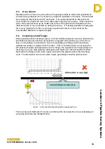
junction. If attenuation readings are made across a junction, a fault will be indicated
because the injected signal will split and part of the signal will travel along the other ‘leg’ of
the pipeline. A good plan of the pipeline will help to identify these anomalies before they
are encountered during a survey.
8.9. Sleeves
When pipelines are ‘sleeved’ under a roadway, the pipeline is encased in a section of
metal pipe of larger diameter which provides protection from mechanical damage.
However, it is still possible to detect wrap faults on the enclosed pipeline provided that:
a) There is no electrical connection between the pipe and the sleeve
b) The sleeve itself has some form of coating (inside and out)
c) The annular space between the pipe and the sleeve is filled with some reasonably
conductive medium (e.g. moist grout)
d) There is a potential electrical path between the ‘filler’ and the surrounding soil
Useful results may be obtained in the absence of some of these conditions, but they
should not be relied upon. Reference readings should not be taken over sleeved sections
of pipeline.
8.10. Effects of ‘Return Current’
When part of the applied signal current escapes through a wrap fault into the soil, it will
travel in the general direction of the Signal Generator earth point. After a short distance,
the return current will become dispersed and virtually undetectable, but close to the fault,
this current may produce a field which will interfere with the field radiating from the
pipeline. This may produce a ‘dip’ in the apparent pipeline current plotted during a close
interval locating survey, i.e. after the sharp fall in signal current (indicating the presence of
an anomaly or fault) the current may return part way to its original level when the effects of
the ‘return current’ are no longer present. This effect is particularly marked when
operating close to the earth point, when the fault is large, and when the pipe itself is large
and with cover of less than 1x the diameter.


