Leaders in Pipelin
e Survey Systems
C
C
C
-
-
-
S
S
S
C
C
C
A
A
A
N
N
N
2
2
2
0
0
0
1
1
1
0
0
0
SYSTEM MANUAL Version 6.03i
44
To start a close interval survey enter the search screen (
) and locate the pipeline as
normal, but rather than press the calculate key (
), press the key marked ‘
close
’
instead. This will reveal the following screen:
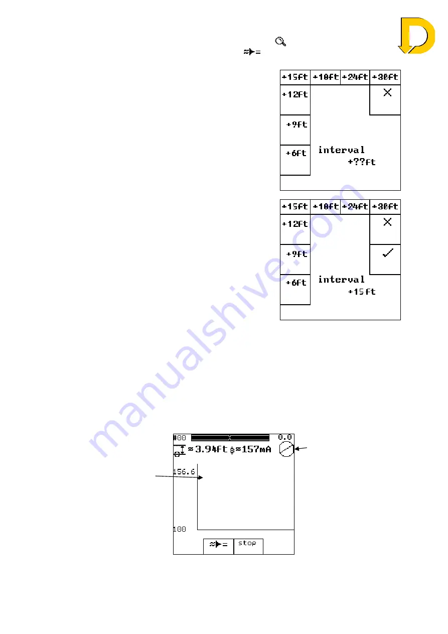
The Surveyor is then asked to choose the interval at
which the Close Interval readings will be taken. It is
very important that the readings
are
taken at the correct
distance chosen, otherwise errors will occur.
Fig. 6.18 – Choosing Spacing
In this example, an interval of 15ft between each
reading is chosen.
To confirm the selection, press or press
³
to choose
a different interval.
Fig. 6.19 – Spacing Selection
Once a selection has been made, the Close Interval survey can begin and the CLOSE
INTERVAL screen is shown – Fig 6.20. The CLOSE INTERVAL screen contains many of
the elements of the SEARCH screen that are already familiar.
As with the SEARCH screen, the Pipeline Position Indicator is shown as a circle and line,
but this time it is located in the top right of the screen with the approximate distance shown
above. The two Overhead Location Bars are also shown, as before, along with the Depth
and Current.
The difference in the
CLOSE INTERVAL
screen is the graph
displays the calculated
current in
real-time
for
each point. As the
Detector reads the
current, a dot is displayed
on the graph representing
the current on the
pipeline.
Fig. 6.20 – Close Interval screen
Check the unit is
overhead by using the
circle and overhead bars
as before.


