Operation (CME)
5-9
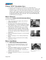
Adding “HTF” to System
Verify that the power supply is correct and the electrical hook
up is as specified in “Setup.”
•
Ensure all breakers are in the “On” position.
•
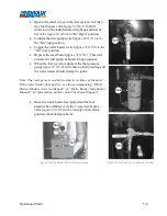
Remove fill/drain hose plug
figure 34
(20-2) from
the fill/drain hose
•
Submerge the fill/drain hose into the bottom of the
barrel/pail or jug or pre-mixed “HTF” (see “Setup”
for heat transfer fluid specification).
•
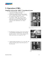
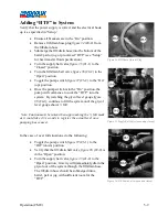
Turn the supply ball valve
figure 35
(21-1) to the
“Closed” position.
•
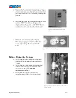
Turn the fill/drain ball valve
figure 36
(22-2) to the
“Open” position.
•
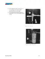
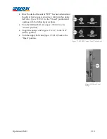
Toggle the pump switch
figure 37
(23-2) to the “On”
(up) position.
•
Once the pump switch is in the “On” position, the
pump will commence to suck the “HTF” into the
system. By watching the glycol level gauge
figure
38
(24-1), continue to fill the system until the glycol
level gauge shows ½ full.
Note: Caution must be taken when approaching the ½ full mark
as it could take 2-3 seconds to register the actual level once
pumping has ceased.
In the case of over full situations, do the following:
•
Toggle the pump switch
figure 37
(23-1) to the
“Off” (down) position.
•
Verify that the fill/drain ball valve
figure 36
(22-2) is
in the “Open” position.
•
Turn the supply ball valve
figure 35
(21-2) to the
“Open” position. Gravity will immediately drain the
glycol out of the system through the fill/drain hose.
The fill/drain hose should be submerged into a
barrel, pail or jug with sufficient room for the
“HTF”.
Figure 34-Fill/Drain Hose & Plug
Figure 35-Supply Ball Valve (open and closed)
Figure 36-Fill/Drain Valve (open and closed)
Содержание 600 GTS Series
Страница 2: ......
Страница 47: ...Appendix 9 3 Electrical Schematics Figure 56 600 GTS sub 40 Electrical Schematic...
Страница 48: ...Appendix 9 4 Figure 57 600 GTS Electrical Schematic...
Страница 49: ...Appendix 9 5 Figure 58 HR2250 Electrical Schematic...
Страница 50: ...Appendix 9 6 Figure 59 Trailer Wiring Schematic...

