Operation (CME)
5-6
Control Settings
Low Flow Situation
Utilizing only one 80 or 200 portable heat exchangers or only one or two circulation line
exchanger loops.
•
Water heater heat exchanger temperature overrun can be expected, therefore initially
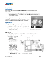
set the aquastat
figure 27
(13-1) at 140°F (60°C) and the high limit switch
figure 27
(13-2) at 200° F (93° C).
Note: A single line heat exchanger loop may not have enough flow
to activate the system flow switch. If this occurs, consider adding
another loop of hose to increase flow and activate the system.
High Flow Situation
Utilizing two or more portable heat exchangers or three or more
circulating line heat exchanger loops.
•
Set the aquastat
figure 27
(13-1) at 190°F (88°C) and
the high limit switch
figure 27
(13-2) between 200°F -
210°F (93°C - 99° C).
Initiate Firing
•
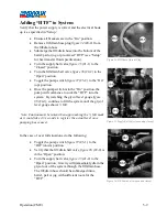
Verify that the “pump switch”
figure 27
(13-3) is in the “On” (up) position.
•
Toggle the water heater switch
figure 27
(13-4) to the “On” (up) position.
•
The burner will proceed
through its firing
sequence.
•
Once the burner is
operating smoothly and
the system pressure is
steady (air has been
eliminated from the
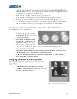
system), monitor the
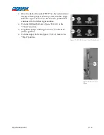
“supply temperature”
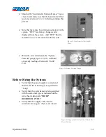
figure 28
(14-1) until
within 10° F of the
aquastat temperature
setting
figure 28
(14-1).
•
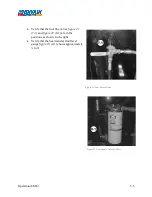
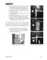
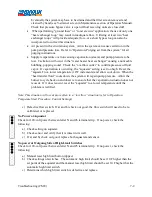
Verify that only one
“heat exchanger loop” or one
Figure 28-Supply Temperature Gauge
Figure 29-Circulation Valve Position
Содержание 600 GTS Series
Страница 2: ......
Страница 47: ...Appendix 9 3 Electrical Schematics Figure 56 600 GTS sub 40 Electrical Schematic...
Страница 48: ...Appendix 9 4 Figure 57 600 GTS Electrical Schematic...
Страница 49: ...Appendix 9 5 Figure 58 HR2250 Electrical Schematic...
Страница 50: ...Appendix 9 6 Figure 59 Trailer Wiring Schematic...

