Operation (CME)
5-2
•
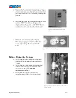
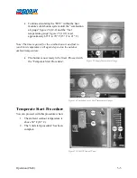
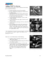
Monitor the “heat transfer fluid sight glass”
figure
18
(4-1) and make sure that the heat transfer fluid
level stays between ¼ to ½ full always during this
process.
•
Note that there may be certain amount of air in the
system. “HTF” levels may change as air is
displaced from the system. Add “HTF” fluid to
maintain ¼ to ½ levels when the fluid is cold.
•
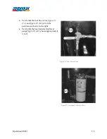
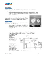
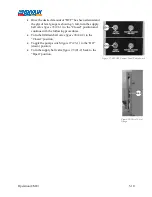
When the air is eliminated, the “System
Pressure” gauge
figure 19
(5-1) will hold
at a steady reading of between 15 to 40
P.S.I.
Before Firing the System
•
Verify that the power supply is correct and
that the electrical hook up is as specified in
“Setup”.
•
Verify that the water heater is being supplied
with the same fuel type as indicated on the
water heater data plate
“LIGHT
OIL/DIESEL FUEL”.
•
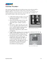
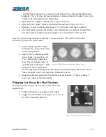
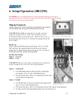
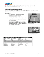
Verify that the “supply” and “return”
isolation valves
figure 20
(6-1) are closed.
Figure 18-Heat Transfer Fluid Sight
Glass
Figure 18-Heat Transfer Fluid Sight
Glass
Figure 19-System Pressure Gauge
Figure 20- Supply & Return Isolation Valve in the
Closed Position
Содержание 600 GTS Series
Страница 2: ......
Страница 47: ...Appendix 9 3 Electrical Schematics Figure 56 600 GTS sub 40 Electrical Schematic...
Страница 48: ...Appendix 9 4 Figure 57 600 GTS Electrical Schematic...
Страница 49: ...Appendix 9 5 Figure 58 HR2250 Electrical Schematic...
Страница 50: ...Appendix 9 6 Figure 59 Trailer Wiring Schematic...

