Troubleshooting (CME)
7-1
7. Troubleshooting (CME)
•
There are 6 green lights on the control panel, which indicate the status of a sequence
of functions while the unit is running.
•
Aquastat and burner light go off and on as the burner cycles.
•
When the burner is on, all green lights should be on. With the burner on, any light
which is not on should be considered burned out.
•
Troubleshoot power issues at the control panel control strip. Remove control panel to
expose terminal strip.
No power at outgoing side of water heater toggle switch
Check for 120-volt power between letter N and #1 on the terminal strip. If no power, check the
following:
a)
Check that the circuit breaker for the water heater has not been switched off.
b)
Check that the toggle switch for the water heater has not been turned off.
c)
Check for power in and out of the breaker and toggle switch.
d)
Check that correct power supply has been connected to the unit. Investigate power
source and be certain that the power characteristics are correct. (115/230 volt, 30 amps,
single phase, 4-conductor, 0’-100’-10 AWG, over 100’-8 AWG)
No Power at Terminal #4 on Low Water Cutoff
Check for 120-volt power between letter N and #2 on the terminal strip. If no power, check the
following:
a)
Low water situation. Check fluid level in tank and add if necessary.
b)
Check fuse in low water cutoff. Replace if required.
No Power at Flow Switch
Check for 120-volt power between letter N and #3 on the terminal strip. If no power, check the
following:
a)
Pump not running. Check pump breaker and toggle switch on control panel. Check for
230 volts at pump motor. If correct power is confirmed at motor, but pump won’t run
refer to “G&L Pumps, Installation, Operation & Maintenance Instructions, 11-
Troubleshooting Chart” for more in depth troubleshooting.
b)
Inadequate flow
•
Check that all valves are open in the fluid-transfer loop. Filter screen may be
plugged. Use flush hose/valve attachment into a bucket while pump is running. For a
quick Y-strainer flush (see Y-strainer in Maintenance section of Operators Manual).
Содержание 600 GTS Series
Страница 2: ......
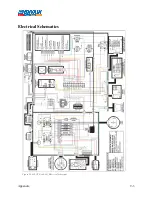
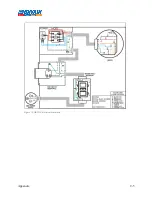
Страница 47: ...Appendix 9 3 Electrical Schematics Figure 56 600 GTS sub 40 Electrical Schematic...
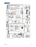
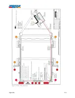
Страница 48: ...Appendix 9 4 Figure 57 600 GTS Electrical Schematic...
Страница 49: ...Appendix 9 5 Figure 58 HR2250 Electrical Schematic...
Страница 50: ...Appendix 9 6 Figure 59 Trailer Wiring Schematic...

