UG6951 / UG6952 / UG6954/ UG6955 / UG6956 / UG6957
SAFEMASTER PRO fieldbus modules
0265998 09.05.2017 LA 822P
11
/
17
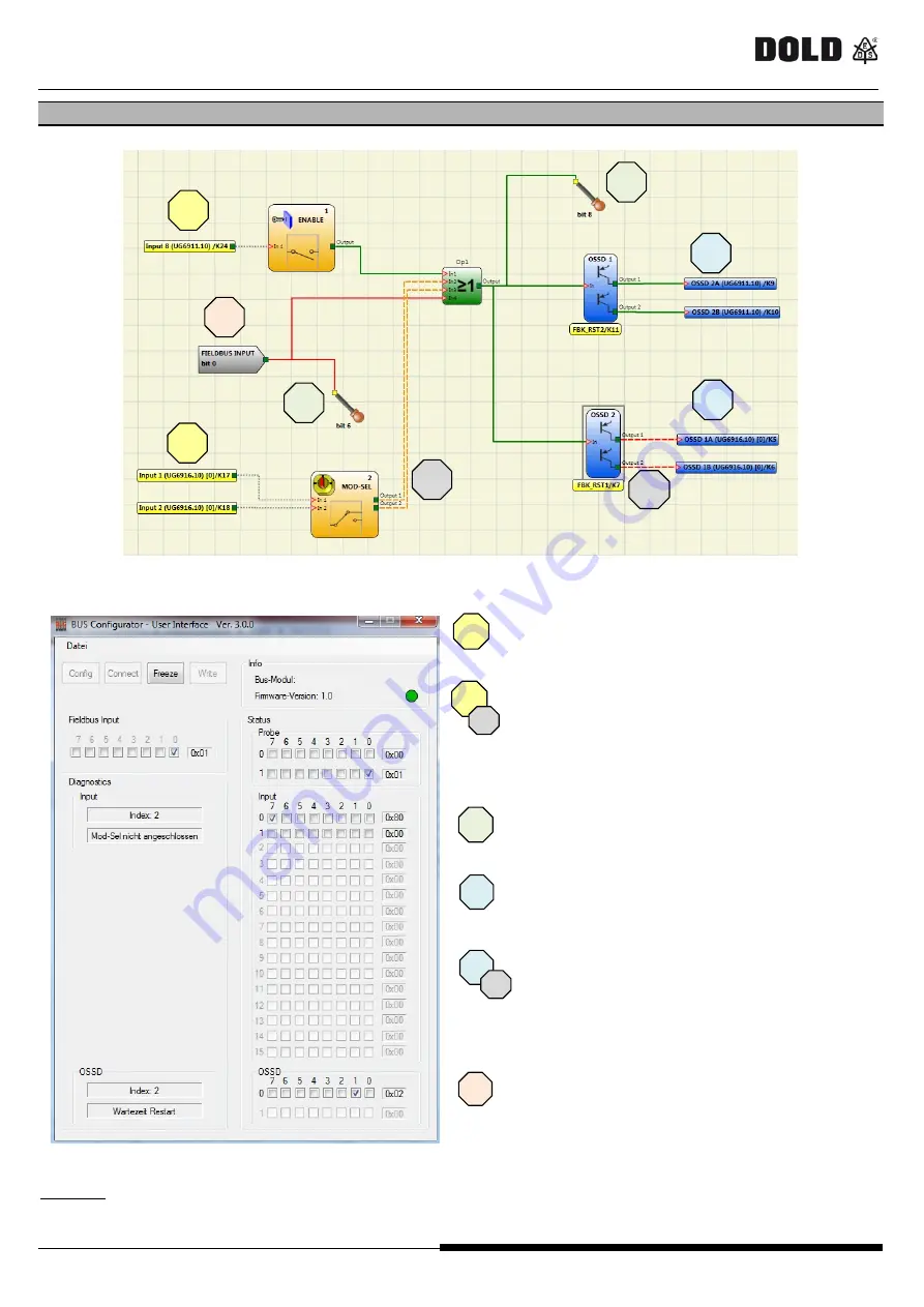
Diagnostic example
Figure
18
: Project example on SAFEMASTER PRO DESIGNER
-
The input 1 ENABLE is connected to Input 8 (terminal
24) oft he control unit UG6911.10 and its status (0 or
1) is shown in the field "Status Input" at bit 7 of the
bytes 0.
-
The input 2 MOD-SEL is connected to inputs 1 and 2
(terminals 17 and 18) of the extension module
UG6916.10. The diagnosis indicates failure (dotted
orange line). The status is indicated in the section
"Status Input" and by the bit pair 0 and 1 of the byte 1.
The diagnosis is displayed in the section "Diagnostics
Input" with index 2 and the corresponding description.
-
The Probe at Bit 6 and Bit 8 are displayed in green and
the corresponding bits are indicated in the section
“Status Probe". Bit 8 is displayed as bit 0 of the
second byte.
-
OSSD 1 is ON and connected to the second output pair
of the control unit UG6911.10 (terminals 9 and 10). Its
status is displayed in section "Status OSSD" at bit 1 of
byte 0.
-
OSSD 2 is OFF and connected to the second output
pair (terminals 5 and 6) of the extension module
UG6916.10. The diagnosis shows that the system is
waiting for a restart. Its status is displayed in section
"Status OSSD" at bit 3 of bytes 0. The diagnosis is
displayed in section "Diagnostics OSSD" with Index 2
and the corresponding description.
-
In section "Fieldbus Input" Bit 0 is selected and as a
result the "Fieldbus Input" Bit 0 in the configuration
plan appears in green color.
Figure
19
Attention:
The function
"Setting of Fieldbus Input"
can only be used with the Bus-Configurator Software via a field bus
module UG6957 (USB). With the modules (UG6951 to UG6956) for other field bus systems the change of these inputs can only
be made via the bus.
1
2
3
5
3
2
4
4
1
3
1
2
1
2
3
3
4
1
4
4
4
5
5
CANOpen
Master Status:


