
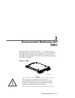
Environmental Monitoring Unit (EMU)
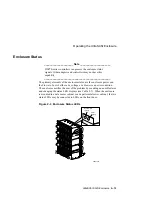
UltraSCSI RAID Enclosure 3–5
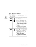
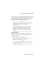
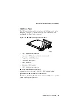
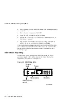
EMU Front Panel
The EMU user interface controls, connectors, and LED displays are on the
front panel. Use Figure 3–3 and the following sections to identify, and
determine the function of each component.
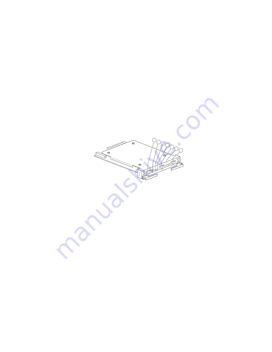
Figure 3–3 EMU Major Component Locations
CXO5774A
1
2
3
4
5
6
7
1. EMU communications connector
2. System fault LED (amber) and alarm control switch
3. Temperature fault LED (amber).
4. Power status LED (green)
5. RS232
Connector
6. Blower fault LEDs (amber)
7. EMU communications connector
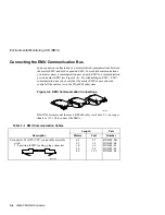
EMU Communications Connectors
A connector (C
ALLOUTS
1 and 7) for EMU—EMU communications.
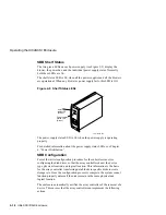
System Fault LED and Alarm Control Switch
The amber system fault LED in the alarm control switch (C
ALLOUT
2) is O
N
whenever an error condition exists.
Содержание StorageWorks UltraSCSI DS-BA370 Series
Страница 18: ...SES Template Word 7 Blank Page Fix by Peter LaQuerre...
Страница 54: ...SES Template Word 7 Blank Page Fix by Peter LaQuerre...
Страница 84: ...SES Template Word 7 Blank Page Fix by Peter LaQuerre...
Страница 120: ...SES Template Word 7 Blank Page Fix by Peter LaQuerre...
Страница 186: ...SES Template Word 7 Blank Page Fix by Peter LaQuerre...


