3–27
RRD42 SCSI ID Jumper Wire Locations . . . . . . . . . . . . . . . .
3–42
3–28
Removing the RRD43 CD–ROM Drive . . . . . . . . . . . . . . . . . .
3–44
3–29
Separating the Mounting Bracket from the RRD43 CD–ROM
Drive . . . . . . . . . . . . . . . . . . . . . . . . . . . . . . . . . . . . . . . . . . .
3–46
3–30
Removing the Upper and Lower Drive-Mounting Shelf
Combination . . . . . . . . . . . . . . . . . . . . . . . . . . . . . . . . . . . . . .
3–49
3–31
Disconnecting the SCSI Cable . . . . . . . . . . . . . . . . . . . . . . . .
3–50
3–32
Disconnecting the DSSI Cable . . . . . . . . . . . . . . . . . . . . . . . .
3–51
3–33
Separating the Upper Drive-Mounting Shelf from the Lower
Drive-Mounting Shelf . . . . . . . . . . . . . . . . . . . . . . . . . . . . . . .
3–53
3–34
Removing the DSSI Cable from the Daughter Board . . . . . . .
3–54
3–35
Removing the DSSI Daughter Board . . . . . . . . . . . . . . . . . . .
3–56
3–36
Removing the DSSI Cable and Daughter Board . . . . . . . . . . .
3–57
3–37
DSSI ID Jumper Locations . . . . . . . . . . . . . . . . . . . . . . . . . .
3–59
3–38
Removing the DSW42 Logic Board . . . . . . . . . . . . . . . . . . . .
3–61
3–39
Removing the DSW42 Input/Output Cable . . . . . . . . . . . . . .
3–62
3–40
Removing the DSW42 Input/Output Module . . . . . . . . . . . . .
3–63
3–41
Removing the DHW42 Logic Board . . . . . . . . . . . . . . . . . . . .
3–65
3–42
Removing the DHW42 Input/Output Cable . . . . . . . . . . . . . .
3–66
3–43
Removing the DHW42 Input/Output Module . . . . . . . . . . . . .
3–67
3–44
Disconnecting the Cables from the CPU Module . . . . . . . . . .
3–69
3–45
Removing the CPU Module . . . . . . . . . . . . . . . . . . . . . . . . . .
3–71
3–46
Removing the Power Supply . . . . . . . . . . . . . . . . . . . . . . . . .
3–74
A–1
Pin Specifications for the Ports on the BA42B System . . . . . .
A–2
Tables
1–1
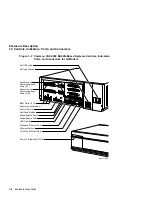
Functions of the Controls, Indicators, Ports, and
Connectors . . . . . . . . . . . . . . . . . . . . . . . . . . . . . . . . . . . . . . .
1–7
1–2
Power Supply dc Outputs . . . . . . . . . . . . . . . . . . . . . . . . . . . .
1–9
1–3
BA42B Communications Options . . . . . . . . . . . . . . . . . . . . . .
1–15
1–4
DSW42-AA Communications Interface Support . . . . . . . . . . .
1–15
1–5
BA42B Mass Storage Devices . . . . . . . . . . . . . . . . . . . . . . . . .
1–17
2–1
Temperature, Humidity, and Altitude Ranges . . . . . . . . . . . .
2–4
2–2
BA42B Electrical Requirements . . . . . . . . . . . . . . . . . . . . . . .
2–5
2–3
Terminal Settings . . . . . . . . . . . . . . . . . . . . . . . . . . . . . . . . . .
2–8
2–4
Terminal Settings . . . . . . . . . . . . . . . . . . . . . . . . . . . . . . . . . .
2–17
3–1
Major FRUs in the BA42B Enclosure . . . . . . . . . . . . . . . . . . .
3–3
viii


