background image

134

Removing and Installing Parts

9

Replace the computer cover ("Replacing the Computer Cover" on page 172).


NOTICE: 

To connect a network cable, first plug the cable into the network wall jack 

and then plug it into the computer.

10

Connect your computer and devices to electrical outlets, and then turn 
them on.

11

When you restart your computer, enter system setup (see "System Setup" 
on page 178). Then, go to the "Drives" section of the BIOS and under 

SATA 0 through 4

, set the SATA port to "

ON

" for the hard drive you 

just installed. This enables the drive. 

See the documentation that came with the drive for instructions on 
installing any software required for drive operation.

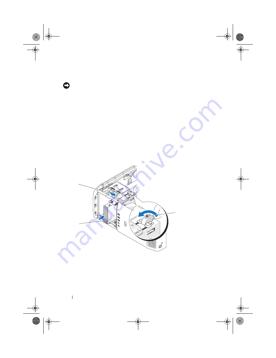
Installing a Hard Drive in the FlexBay

The top FlexBay drive on your system can hold an additional hard drive. 

1

Follow the procedures in "Before You Begin" on page 99.

2

Remove the computer cover (see "Removing the Computer Cover" on 
page 101). 

1

hard drive

2

sliding plate lever

3

flexbay knob (the default position)

2

1

3

book.book  Page 134  Tuesday, November 27, 2007  10:29 AM

Содержание XPS 420

Страница 1: ...w w w d e l l c o m s u p p o r t d e l l c o m Dell XPS 420 Owner s Manual Model DC01L book book Page 1 Tuesday November 27 2007 10 29 AM ...

Страница 2: ... TravelLite the Dell Media Xcelerator Yours Is Here and StrikeZone are trademarks of Dell Inc Intel Pentium Intel Core 2 Extreme Intel Core 2 Duo Intel Core 2 Quad Intel SpeedStep and Intel ViiV are either trademarks or registered trademarks of Intel Corporation Microsoft Windows Windows Vista Outlook SideShow and the Windows Vista Start button are either trademarks or registered trademarks of Mic...

Страница 3: ... Connecting a Monitor Without an Adapter 25 Connecting a Monitor With an Adapter 26 Connecting Two or More Monitors 28 Connecting a TV 29 Changing the Display Settings 30 About Your RAID Configuration 30 RAID Level 0 Configuration 30 RAID Level 1 Configuration 31 Configuring Your Computer for RAID 32 Using the Intel RAID Option ROM Utility 33 Using the Intel Application Accelerator 36 Dell DataSaf...

Страница 4: ...edia 45 Using Blank CDs and DVDs 45 Helpful Tips 46 Using a Media Card Reader 47 Understanding the Media Xcelerator Optional 49 Understanding Windows SideShow and the LCD display 50 Configuring the LCD display 51 Adding Gadgets To LCD Display Menu 51 Setting Up a Printer 52 Printer Cable 52 Connecting a USB Printer 52 Connecting to the Internet 54 Setting Up Your Internet Connection 54 Network Set...

Страница 5: ... 61 Coin Cell Battery Problems 61 Drive Problems 62 E Mail Modem and Internet Problems 63 Error Messages 64 IEEE 1394a Device Problems 65 Keyboard Problems 65 Lockups and Software Problems 66 Memory Problems 68 Mouse Problems 68 Network Problems 69 Power Problems 69 Printer Problems 71 Scanner Problems 71 Sound and Speaker Problems 72 Video and Monitor Problems 73 Power Lights 75 Diagnostic Lights...

Страница 6: ...91 Using the Drivers and Utilities Media 92 Troubleshooting Software and Hardware Problems in the Microsoft Windows Vista Operating System 93 Restoring Your Operating System 94 Using Microsoft Windows System Restore 94 Using Dell Factory Image Restore 95 Using the Operating System Media 96 Troubleshooting LCD Display Problems 98 4 Removing and Installing Parts 99 Before You Begin 99 Recommended To...

Страница 7: ...Panel Insert 126 Replacing the Drive Panel 127 Drives 128 General Installation Guidelines 128 Hard Drive 129 Removing a Hard Drive 129 Installing a Hard Drive 130 Adding a Second Hard Drive 132 Installing a Hard Drive in the FlexBay 134 Removing a Hard Drive From the FlexBay 135 Floppy Drive 136 Removing a Floppy Drive 136 Installing a Floppy Drive 138 Media Card Reader 140 Removing a Media Card R...

Страница 8: ...Installing the Processor Fan 152 Removing the Card Fan 152 Installing the Card Fan 154 Processor 154 Removing the Processor 154 Installing the Processor 155 System Board 157 Removing the System Board 157 Installing the System Board 158 Power Supply 160 Power Supply PSU DC Connector Pin Assignments 160 Removing the Power Supply 165 Installing the Power Supply 166 Front I O Panel 167 Front I O Panel...

Страница 9: ...nce 186 Clearing Forgotten Passwords 188 Clearing CMOS Settings 190 Cleaning Your Computer 191 Computer Keyboard and Monitor 191 Mouse 191 Floppy Drive 192 CDs and DVDs 192 FCC Notices U S Only 193 Class A 193 Class B 194 FCC Identification Information 194 Getting Help 195 Obtaining Assistance 195 Technical Support and Customer Service 196 DellConnect 196 Online Services 196 book book Page 9 Tuesd...

Страница 10: ... Order Status Service 197 Problems With Your Order 197 Product Information 197 Returning Items for Warranty Repair or Credit 198 Before You Call 198 Contacting Dell 200 Glossary 201 Index 219 book book Page 10 Tuesday November 27 2007 10 29 AM ...

Страница 11: ...d Utilities Media Documentation and drivers are already installed on your computer You can use the Drivers and Utilities media to reinstall drivers see Reinstalling Drivers and Utilities on page 91 access your documentation or run the Dell Diagnostics see Dell Diagnostics on page 86 Readme files may also be included on your media to provide last minute updates about technical changes to your compu...

Страница 12: ...ervice Tag and Microsoft Windows Product Key These labels are located on your computer Use the Service Tag to identify your computer when you use support dell com or contact support Enter the Express Service Code to direct your call when contacting support NOTE As an increased security measure the newly designed Microsoft Windows license label incorporates a missing portion or hole to discourage r...

Страница 13: ...should also reinstall the DSS utility DSS automatically detects your computer and operating system and installs the updates appropriate for your configuration providing critical updates for your operating system and support for Dell 3 5 inch USB floppy drives Intel Pentium M processors optical drives and USB devices DSS is necessary for correct operation of your Dell computer Dell Support Website ...

Страница 14: ... screen How to reinstall my operating system Operating System Media The operating system is already installed on your computer To reinstall your operating system use the Operating System media see Restoring Your Operating System on page 94 After you reinstall the operating system use the Drivers and Utilities media to reinstall drivers for the devices that came with your computer The operating sys...

Страница 15: ...g Up and Using Your Computer 15 Setting Up and Using Your Computer Front and Back View of the Computer Front View 1 16 17 15 3 4 5 2 6 8 14 13 12 7 10 9 11 book book Page 15 Tuesday November 27 2007 10 29 AM ...

Страница 16: ...pressed 6 vents For adequate cooling do not block any of the vents NOTICE Ensure that there is a minimum of two inches of space between all vents and any object near the vents NOTICE Keep the vent area clean and dust free to ensure that the system is adequately ventilated Use only a dry cloth to clean the vent area to avoid water damage to the system 7 IEEE 1394 connector Use the IEEE 1394 connect...

Страница 17: ...video input output device with or without a graphics accelerator device floppy drive or an additional hard drive 13 5 25 inch drive bays 2 Can hold CD RW DVD audio or video input or output with or without graphics accelerator device DVD RW or Blu ray Disc 14 hard drive activity light The hard drive light is on when the computer reads data from or writes data to the hard drive The light may also be...

Страница 18: ... USB connectors for devices that you connect occasionally such as flash memory keys cameras or bootable USB devices For more information on bootable USB devices see Boot Sequence on page 186 It is recommended that you use the back USB connectors for devices that typically remain connected such as printers and keyboards 4 IEEE 1394 connector Use the IEEE 1394 connector for high speed data devices s...

Страница 19: ...connectors Connect appropriate audio devices see Back I O Connectors on page 20 3 USB connectors Recommended for devices that typically remain connected such as printers and keyboards 4 S PDIF RCA Connects to external digital stereo speakers 5 eSATA Use it to connect to additional storage devices 1 2 3 4 5 6 7 8 book book Page 19 Tuesday November 27 2007 10 29 AM ...

Страница 20: ...a network or broadband device 1 IEEE 1394 Use the IEEE 1394 connector for high speed data devices such as digital video cameras and external storage devices 2 eSATA Use this connector to connect to external SATA storage devices 3 S PDIF RCA Connects to external digital stereo speakers 4 USB connectors 4 rear quad Use the back rear quad USB connectors for devices that typically remain connected suc...

Страница 21: ...he card and on the back of the computer when setting up multiple network connections such as a separate intra and extranet NOTE It is recommended that you use Category 5 wiring and connectors for your network If you must use Category 3 wiring force the network speed to 10 Mbps to ensure reliable operation 7 network activity light Flashes a yellow light when the computer is transmitting or receivin...

Страница 22: ...th a sound card use the connector on the card 12 center subwoof er LFE connector Use the orange center subwoofer connector to attach a center speaker or a single subwoofer On computers with a sound card use the connector on the card NOTE The LFE Low Frequency Effects Audio channel found in digital surround sound audio schemes carries only low frequency information of 80 Hz and below The LFE channe...

Страница 23: ...ur enclosure has doors they need to be of a type that allows at least 30 airflow through the enclosure front and back If your computer is installed in a corner on a desk or under a desk leave at least 5 1 centimeters 2 inch of clearance from the back of the computer to the wall to permit the airflow required for proper ventilation book book Page 23 Tuesday November 27 2007 10 29 AM ...

Страница 24: ...ety instructions in the Product Information Guide CAUTION To reduce the risk of fire electric shock or injury do not overload an electrical outlet power strip or convenience receptacle The total ampere rating of all products plugged into an electrical outlet power strip or other receptacle should not exceed 80 percent of the branch circuit rating NOTE Your video card has three different ports a DV...

Страница 25: ... corner of the Start menu as shown below and then click Shut Down The computer turns off after the operating system shutdown process is complete 3 Ensure that the computer and all attached devices are turned off If your computer and attached devices did not automatically turn off when you shut down your operating system press and hold the power button for about 4 seconds to turn them off Disconnec...

Страница 26: ... With an Adapter CAUTION Before you perform any of the procedures in this section follow the safety instructions in the Product Information Guide NOTE In order to connect a monitor with a VGA connector to the DVI port on the back of your computer a DVI to VGA adapter is required 1 Save and close all open files and exit all open programs 2 Shut down the operating system In Windows Vista click Start...

Страница 27: ...down your operating system press and hold the power button for about 4 seconds to turn them off 4 Connect the DVI to VGA adapter to the VGA connector on your monitor and then connect the other end of the adapter to the white DVI port on the back of the computer 1 DVI white connector 2 DVI to VGA adapter optional 3 TV OUT connector 2 1 3 book book Page 27 Tuesday November 27 2007 10 29 AM ...

Страница 28: ...t automatically turn off when you shut down your operating system press and hold the power button for about 4 seconds to turn them off 4 Connect two or more monitors to the appropriate DVI or VGA ports on the back of the computer NOTE In order to connect a monitor with a VGA connector to the DVI port on the back of your computer a DVI to VGA adapter is required To connect two or more monitors dire...

Страница 29: ...operating system In Windows Vista click Start click the arrow in the lower right corner of the Start menu as shown below and then click Shut Down The computer turns off after the operating system shutdown process is complete 3 Ensure that the computer and all attached devices are turned off If your computer and attached devices did not automatically turn off when you shut down your operating syste...

Страница 30: ...e in the digital photography and audio industries NOTE RAID levels do not represent a hierarchy A RAID level 1 configuration is not inherently better or worse than a RAID level 0 configuration The drives in a RAID configuration should be the same size in order to ensure that the larger drive does not contain unallocated and therefore unusable space RAID Level 0 Configuration NOTICE Because RAID le...

Страница 31: ...y the number of drives in the configuration RAID Level 1 Configuration A RAID level 1 configuration uses a data redundancy storage technique known as mirroring to enhance data integrity When data is written to the primary drive the data is also duplicated or mirrored on the second drive in the configuration RAID level 1 sacrifices high data access rates for its data redundancy advantages hard driv...

Страница 32: ...on page 30 For instructions on how to install a hard drive see Installing a Hard Drive on page 130 You can use one of two methods to configure RAID hard drive volumes The first method uses the Intel RAID Option ROM utility and is performed before you install the operating system onto the hard drive The second method uses the Intel Application Accelerator and is performed after you have installed t...

Страница 33: ...of any size may be used to create a RAID configuration using the Intel RAID Option ROM utility Ideally however the drives should be of equal size to avoid unallocated or unused space For an explanation of RAID levels see About Your RAID Configuration on page 30 Creating a RAID Level 0 Configuration NOTICE The following procedure will result in the loss of all data on your hard drives Back up any d...

Страница 34: ...eate the RAID volume 11 Confirm that the correct volume configuration is displayed on the main Intel RAID Option ROM utility screen 12 Press the up and down arrow keys to select Exit and then press Enter 13 Install the operating system See Reinstalling Windows Vista on page 97 Creating a RAID Level 1 Configuration 1 Set your computer to RAID enabled mode see Setting Your Computer to RAID Enabled M...

Страница 35: ...The following procedure will result in the loss of all data on the hard drives in your RAID configuration Back up any data you want to keep before continuing NOTICE If your computer currently boots to RAID and you delete the RAID volume in the Intel RAID Option ROM utility your computer will become unbootable 1 Press Ctrl I when you are prompted to enter the Intel RAID Option ROM utility 2 Use the...

Страница 36: ...ation NOTICE The following procedure will result in the loss of all data on the hard drives in your RAID configuration Back up any data you want to keep before continuing 1 Set your computer to RAID enabled mode see Setting Your Computer to RAID Enabled Mode on page 33 2 Click Start and point to Programs Intel R Application Accelerator Intel Matrix Storage Manager to launch the Intel Storage Utili...

Страница 37: ...menu option you have not yet set your computer to RAID enabled mode see Setting Your Computer to RAID Enabled Mode on page 33 3 On the Actions menu select Create RAID Volume to launch the Create RAID Volume Wizard 4 Click Next at the first screen 5 Confirm the volume name select RAID 1 as the RAID level and then click Next to continue 6 On the Select Volume Location screen click the first hard dri...

Страница 38: ...ing to a RAID Level 0 Configuration 1 Set your computer to RAID enabled mode see Setting Your Computer to RAID Enabled Mode on page 33 2 Click the Start button and point to All Programs Intel R Application Accelerator Intel Matrix Storage Manager to launch the Intel Storage Utility NOTE If you do not see an Actions menu option you have not yet set your computer to RAID enabled mode see Setting You...

Страница 39: ...on page 33 2 Click the Start button and point to All Programs Intel R Application Accelerator Intel Matrix Storage Manager to launch the Intel Storage Utility NOTE If you do not see an Actions menu option you have not yet set your computer to RAID enabled mode see Setting Your Computer to RAID Enabled Mode on page 33 3 On the Actions menu click Create RAID Volume From Existing Hard Drive to launch...

Страница 40: ... the Start button and point to Programs Intel R Application Accelerator Intel Matrix Storage Manager to launch the Intel Storage Utility 2 Right click the hard drive you want to mark as a spare hard drive 3 Click Mark as Spare To remove a drive as a spare hard drive 1 Right click the spare hard drive icon 2 Click Reset Hard Drive to Non RAID Rebuilding a Degraded RAID Level 1 Configuration If your...

Страница 41: ... an entire hard drive and the Intel Matrix Storage Console RAID allows for continued functionality in the case of a single hard drive failure Intel Viiv Technology Optional Intel Viiv technology is a technology aimed at the digital home enthusiast that includes A BIOS that supports Intel Quick Resume Technology Device drivers This technology allows the user s system to quickly return to an active ...

Страница 42: ... the Quick Resume feature Enabling the QRT Feature in the Operating System 1 Click the Start button then click Control Panel 2 Click the Away tab 3 Ensure that the check boxes for Enable away mode and Options are checked 4 Click the Advanced tab 5 From the When I press the power button on my computer drop down menu select Do Nothing 6 From the When I press the sleep button on my computer drop down...

Страница 43: ...e media A CD player includes the following basic buttons A DVD player includes the following basic buttons Play Move backward within the current track Pause Move forward within the current track Stop Go to the previous track Eject Go to the next track Stop Restart the current chapter Play Fast forward Pause Fast reverse Advance a single frame while in pause mode book book Page 43 Tuesday November ...

Страница 44: ... how to make an exact copy of a CD or DVD using Roxio Creator Plus Dell Edition You can also use Roxio Creator Plus for other purposes such as creating music CDs from audio files stored on your computer or backing up important data For help open Roxio Creator Plus and then click the question mark icon in the upper right corner of the window NOTE CD RW DVD combo drives cannot write to DVD media If ...

Страница 45: ...omatically ejects How to Copy a Blu ray Disc BD Media For information on how to use the BD media refer to the manual that accompanies the product Using Blank CDs and DVDs CD RW drives can write to CD recording media only including high speed CD RW media while DVD writable drives can write to both CD and DVD recording media Use blank CD Rs to record music or permanently store data files After the m...

Страница 46: ...y available DVD players used in home theater systems may not support all available DVD formats For a list of formats supported by your DVD player see the documentation provided with your DVD player or contact the manufacturer Do not burn a blank CD R or CD RW to its maximum capacity for example do not copy a 650 MB file to a blank 650 MB CD The CD RW drive needs 1 2 MB of blank space to finalize t...

Страница 47: ... Before you perform any of the procedures in this section follow the safety instructions in the Product Information Guide Use the media card reader to transfer data directly to your computer The media card reader supports the following memory types xD Picture card SmartMedia card SMC CompactFlash card Type I and II CF I II MicroDrive card SecureDigital card SD MiniSD card MultiMediaCard MMC Reduce...

Страница 48: ... is completely seated in the connector If you encounter resistance remove the card check for proper orientation and then try again 1 xD Picture card and SmartMedia Card SMC 2 Memory Stick MS MS Pro MS Duo MS Pro Duo 3 Secure Digital card SD miniSD MultiMedia Card MMC RS MMC 4 CompactFlash card Type I and II CF I II and MicroDrive card 1 2 3 4 book book Page 48 Tuesday November 27 2007 10 29 AM ...

Страница 49: ...ion to low bit rate MPEG 4 formats for portable video devices Features supported include Improved system availability through CPU offloading to Xcelerator Quicker DVD creation with improved fit to disk capability Transcode High Definition MPEG 2 video clips to MPEG 2 or MPEG 4 standard definition Faster conversions of movies into PC or PMP formats Transrate MPEG 2 video clips to a lower bit rate t...

Страница 50: ...e computer onto devices such as the LCD display Gadgets allow you to view information from your computer regardless of whether it is on off or sleeping Some of the default gadgets available on the LCD allow you to browse web pictures view photos stored on your system play or browse audio and video files set reminders and alarms monitor PC settings and set a real time count down clock 1 network ind...

Страница 51: ...s current or changeable configuration information for your computer 2 On the system setup screen navigate to LCD display and change settings to On 3 Exit setup NOTE The LCD display simultaneously starts when the system is next powered on Adding Gadgets To LCD Display Menu The LCD display menu includes a list of all the gadgets shipped with your system It also allows you to remove existing gadgets ...

Страница 52: ...r connects to your computer with either a USB cable or a parallel cable Your printer may not come with a printer cable so if you purchase a cable separately ensure that it is compatible with your printer and computer If you purchased a printer cable at the same time you purchased your computer the cable may arrive in the computer s shipping box Connecting a USB Printer NOTE You can connect USB dev...

Страница 53: ...er Click the Windows Vista Start button and click Network Add a printer to start the Add Printer Wizard 5 Install the printer driver if necessary See Reinstalling Drivers and Utilities on page 91 and the documentation that came with your printer 1 USB connector on computer 2 USB connector on printer 3 USB printer cable 2 1 3 book book Page 53 Tuesday November 27 2007 10 29 AM ...

Страница 54: ...n system Dial up connections that provide Internet access through a telephone line Dial up connections are considerably slower than DSL and cable or satellite modem connections Wireless LAN connections that provide Internet access using Bluetooth wireless technology If you are using a dial up connection connect a telephone line to the modem connector on your computer and to the telephone wall jack...

Страница 55: ...ick Connect to the Internet The Connect to the Internet window appears 4 Click either Broadband PPPoE or Dial up depending on how you want to connect Choose Broadband if you will use a DSL satellite modem cable TV modem or Bluetooth wireless technology connection Choose Dial up if you will use a dial up modem or ISDN NOTE If you do not know which type of connection to select click Help me choose o...

Страница 56: ... on and you are not using it You can reduce power to just the monitor or the hard drive or you can use sleep mode or hibernate mode to reduce power to the entire computer When the computer exits from a power conservation mode it returns to the operating state it was in prior to entering the mode Sleep Mode Sleep mode conserves power by turning off the display and the hard drive after a predetermin...

Страница 57: ...nd then click Hibernate NOTE If Hybrid Sleep is ON then Hibernate will no longer appear on the shutdown menu in Vista To enable hibernation click Start open Search box and type powercfg exe hibernate ON press Ctrl Shift Enter To disable hibernation click Start open Search box and type powercfg exe hibernate Off press Ctrl Shift Enter Configuring Power Management Settings You can use the Windows Po...

Страница 58: ...58 Setting Up and Using Your Computer book book Page 58 Tuesday November 27 2007 10 29 AM ...

Страница 59: ... hand When an application does not require full performance significant amounts of power can be saved Performance is designed to still be responsive with maximum processor performance being delivered when required and automatic power savings when possible Windows Vista automatically sets Intel Speedstep technologies in the Dell Recommended Balanced and Power Saver power plans It is disabled in the...

Страница 60: ...60 Optimizing for Greater Performance book book Page 60 Tuesday November 27 2007 10 29 AM ...

Страница 61: ...f you set your Dell computer to the Windows Classic view Coin Cell Battery Problems CAUTION There is a danger of a new coin battery exploding if it is incorrectly installed Replace the coin battery only with the same or equivalent type recommended by the manufacturer Discard used batteries according to the manufacturer s instructions CAUTION Before you begin any of the procedures in this section f...

Страница 62: ...l drive problems NOTE High speed optical drive vibration is normal and may cause noise which does not indicate a defect in the drive or the media NOTE Because of different regions worldwide and different disc formats not all DVD titles work in all DVD drives ADJUST THE WINDOWS VOLUME CONTROL Click the speaker icon in the lower right corner of your screen Ensure that the volume is turned up by clic...

Страница 63: ... SECURITY SETTINGS If you cannot open your e mail attachments 1 In Outlook Express click Tools Options Security 2 Click Do not allow attachments to remove the checkmark as needed CHECK THE TELEPHONE LINE CONNECTION CHECK THE TELEPHONE JACK CONNECT THE MODEM DIRECTLY TO THE TELEPHONE WALL JACK USE A DIFFERENT TELEPHONE LINE Verify that the telephone line is connected to the jack on the modem the ja...

Страница 64: ...ce provider Error Messages CAUTION Before you begin any of the procedures in this section follow the safety instructions in the Product Information Guide If the error message is not listed see the documentation for the operating system or the program that was running when the message appeared A FILENAME CANNOT CONTAIN ANY OF THE FOLLOWING CHARACTERS Do not use these characters in filenames A REQUI...

Страница 65: ...CE IS RECOGNIZED BY WINDOWS 1 Click Start Control Panel Hardware and Sound 2 Click Device Manager If your IEEE 1394a device is listed Windows recognizes the device IF YOU HAVE PROBLEMS WITH A DELL IEEE 1394A DEVICE Contact Dell see Contacting Dell on page 200 IF YOU HAVE PROBLEMS WITH AN IEEE 1394A DEVICE NOT PROVIDED BY DELL Contact the IEEE 1394a device manufacturer Keyboard Problems CAUTION Bef...

Страница 66: ...y instructions in the Product Information Guide The computer does not start up CHECK THE DIAGNOSTIC LIGHTS See Diagnostic Lights on page 76 ENSURE THAT THE POWER CABLE IS FIRMLY CONNECTED TO THE COMPUTER AND TO THE ELECTRICAL OUTLET The computer stops responding NOTICE You may lose data if you are unable to perform an operating system shutdown TURN THE COMPUTER OFF If you are unable to get a respo...

Страница 67: ...ey on your keyboard or moving your mouse press and hold the power button for at least 8 to 10 seconds until the computer turns off and then restart your computer Other software problems CHECK THE SOFTWARE DOCUMENTATION OR CONTACT THE SOFTWARE MANUFACTURER FOR TROUBLESHOOTING INFORMATION Ensure that the program is compatible with the operating system installed on your computer Ensure that your comp...

Страница 68: ...sure that you are following the memory installation guidelines see Installing Memory on page 106 Ensure that the memory you are using is supported by your computer For more information about the type of memory supported by your computer see Memory on page 104 Run the Dell Diagnostics see Dell Diagnostics on page 86 Mouse Problems CAUTION Before you begin any of the procedures in this section follo...

Страница 69: ...nserted into the network connector on the back of the computer and the network jack CHECK THE NETWORK LIGHTS ON THE BACK OF THE COMPUTER If the link integrity light is off see Controls and Lights on page 176 no network communication is occurring Replace the network cable RESTART THE COMPUTER AND LOG ON TO THE NETWORK AGAIN CHECK YOUR NETWORK SETTINGS Contact your network administrator or the perso...

Страница 70: ...d Components on page 103 IF THE POWER LIGHT IS BLINKING AMBER The computer is receiving electrical power but an internal power problem may exist Ensure that the voltage selection switch is set to match the AC power at your location if applicable Ensure that all components and cables are properly installed and securely connected to the system board see System Board Components on page 103 IF THE POW...

Страница 71: ... Hardware and Sound Printer 2 If the printer is listed right click the printer icon 3 Click Properties and click Ports 4 Adjust the settings as needed REINSTALL THE PRINTER DRIVER SEE THE PRINTER DOCUMENTATION FOR INFORMATION ON REINSTALLING THE PRINTER DRIVER Scanner Problems CAUTION Before you begin any of the procedures in this section follow the safety instructions in the Product Information G...

Страница 72: ... THAT THE SUBWOOFER AND THE SPEAKERS ARE TURNED ON See the setup diagram supplied with the speakers If your speakers have volume controls adjust the volume bass or treble to eliminate distortion ADJUST THE WINDOWS VOLUME CONTROL Click or double click the speaker icon in the lower right corner of your screen Ensure that the volume is turned up and that the sound is not muted DISCONNECT HEADPHONES F...

Страница 73: ... If you remove the card store it in a safe and secure location For information about your graphics card go to support dell com The screen is blank NOTE For troubleshooting procedures see the monitor s documentation The screen is difficult to read CHECK THE MONITOR CABLE CONNECTION Ensure that the monitor cable is connected to the correct graphics card for dual graphics card configurations If you a...

Страница 74: ...subwoofer ensure that the subwoofer is positioned at least 60 centimeters 2 feet away from the monitor MOVE THE MONITOR AWAY FROM EXTERNAL POWER SOURCES Fans fluorescent lights halogen lamps and other electrical devices can cause the screen image to appear shaky Turn off nearby devices to check for interference ROTATE THE MONITOR TO ELIMINATE SUNLIGHT GLARE AND POSSIBLE INTERFERENCE ADJUST THE WIN...

Страница 75: ...d the electrical outlet If the computer is plugged into a power strip ensure that the power strip is plugged into an electrical outlet and that the power strip is turned on Bypass power protection devices power strips and power extension cables to verify that the computer turns on properly Ensure that the electrical outlet is working by testing it with another device such as a lamp Ensure that the...

Страница 76: ...ezel see Front View on page 15 When the computer starts normally the lights flash before turning off If the computer malfunctions the sequence of the lights help to identify the problem NOTE After the computer completes POST all four lights turn off before booting to the operating system Light Pattern Problem Description Suggested Resolution The computer is in a normal off condition or a possible ...

Страница 77: ...ry of the same type into your computer see Installing Memory on page 106 If the problem persists contact Dell see Contacting Dell on page 200 A possible graphics card failure has occurred Reseat any installed graphics cards see Cards on page 109 If available install a working graphics card into your computer If the problem persists contact Dell see Contacting Dell on page 200 A possible floppy dri...

Страница 78: ...nstall working memory of the same type into your computer see Installing Memory on page 106 If the problem persists contact Dell see Contacting Dell on page 200 Memory modules are detected but a memory configuration or compatibility error has occurred Ensure that no special requirements for memory module connector placement exist see Memory on page 104 Ensure that the memory you are using is suppo...

Страница 79: ...oved then remove a different card and restart the computer 3 Repeat this process for each expansion card installed If the computer starts normally troubleshoot the last card removed from the computer for resource conflicts see Troubleshooting Software and Hardware Problems in the Microsoft Windows Vista Operating System on page 93 4 If the problem persists contact Dell see Contacting Dell on page ...

Страница 80: ...rive or hard drive check the device to make sure it is functioning properly If the operating system is attempting to boot from a device such as the floppy drive or optical drive check system setup see System Setup on page 178 to ensure the boot sequence is correct for the devices installed on your computer If the problem persists contact Dell see Contacting Dell on page 200 Light Pattern Problem D...

Страница 81: ...the following beep code errors see Contacting Dell on page 200 for instructions on obtaining technical assistance Code Cause 1 3 1 through 2 4 4 Memory not being properly identified or used 4 3 1 Memory failure above address 0FFFFh Code Cause 1 1 2 Microprocessor register failure 1 1 3 NVRAM read write failure 1 1 4 ROM BIOS checksum failure 1 2 1 Programmable interval timer failure 1 2 2 DMA init...

Страница 82: ...lure 4 2 1 No timer tick 4 2 2 Shutdown failure 4 2 3 Gate A20 failure 4 2 4 Unexpected interrupt in protected mode 4 3 1 Memory failure above address 0FFFFh 4 3 3 Timer chip counter 2 failure 4 3 4 Time of day clock stopped 4 4 1 Serial or parallel port test failure 4 4 2 Failure to decompress code to shadowed memory 4 4 3 Math coprocessor test failure 4 4 4 Cache test failure Code Cause book boo...

Страница 83: ...circuitry in the memory has occurred Reseat the memory modules see Memory on page 104 C Drive Error C Drive Failure The hard drive is not working or is not configured correctly Ensure that the hard drive is installed correctly in the computer see Drives on page 128 and defined correctly in the system setup program see System Setup on page 178 Cache Memory Bad Do Not Enable Cache The cache memory i...

Страница 84: ... the system configuration and then restart the computer Diskette Boot Failure Drive A or B is present but has failed the BIOS POST Ensure that the drive is installed correctly in the computer see Drives on page 128 and defined correctly in the system setup program see System Setup on page 178 Check the interface cable at both ends DMA Error DMA 1 Error DMA 2 Error Error in the DMA controller on th...

Страница 85: ...rupt channel on the system board failed to POST The keyboard or system board may need to be replaced Invalid Boot Diskette The operating system cannot be located on drive A or drive C Enter the system setup program see System Setup on page 178 and confirm that drive A or drive C is properly identified Keyboard Error The BIOS has detected a stuck key Ensure that nothing is resting on the keyboard i...

Страница 86: ...u print these procedures before you begin Start Dell Diagnostics from your hard drive or from the Drivers and Utilities media KB Interface Error An error occurred with the keyboard connector Ensure that nothing is resting on the keyboard if a key appears to be stuck carefully pry it up If the problem persists you may need to replace the keyboard No ROM Basic The operating system cannot be located ...

Страница 87: ...gnostics From the Drivers and Utilities Media on page 88 4 Press any key to start the Dell Diagnostics from the diagnostics utility partition on your hard drive NOTE The Quickboot feature changes the boot sequence for the current boot only Upon restart the computer boots according to the boot sequence specified in system setup 5 At the Dell Diagnostics Main Menu left click with the mouse or press ...

Страница 88: ...ption from the menu that appears and press Enter 5 Type 1 to start the CD menu and press Enter to proceed 6 Select Run the 32 Bit Dell Diagnostics from the numbered list If multiple versions are listed select the version appropriate for your computer 7 When the Dell Diagnostics Main Menu appears select the test you want to run NOTE Write down any error codes and problem descriptions exactly as the...

Страница 89: ...he following table for more information Option Function Express Test Performs a quick test of system devices The test typically takes 10 to 20 minutes and requires no interaction on your part Run Express Test first to increase the possibility of tracing the problem quickly Extended Test Performs a thorough check of system devices The test typically takes an hour or more Custom Test Use to test a s...

Страница 90: ...ers for operating systems that are not on your computer Ensure that you are installing software appropriate for your operating system Tab Function Results Displays the results of the test and any error conditions encountered Errors Displays error conditions encountered error codes and the problem description Help Describes the test and any requirements for running the test Configuration Displays y...

Страница 91: ...vice icon If an exclamation point is next to the device name you may need to reinstall the driver or install a new driver see Reinstalling Drivers and Utilities on page 91 Reinstalling Drivers and Utilities NOTICE The Dell Support website at support dell com and your Drivers and Utilities media provide approved drivers for Dell computers If you install drivers obtained from other sources your comp...

Страница 92: ...zard Complete window appears remove the Drivers and Utilities media and click Finish to restart the computer 4 When you see the Windows desktop reinsert the Drivers and Utilities media 5 At the Welcome Dell System Owner screen click Next NOTE The Drivers and Utilities media displays drivers only for hardware that came installed in your computer If you installed additional hardware the drivers for ...

Страница 93: ...ting Software and Hardware Problems in the Microsoft Windows Vista Operating System If a device is either not detected during the operating system setup or is detected but incorrectly configured you can use the Hardware Troubleshooter to resolve the incompatibility To start the Hardware Troubleshooter 1 Click the Windows Vista Start button and click Help and Support 2 Type hardware troubleshooter ...

Страница 94: ... not resolve your operating system problem Using Microsoft Windows System Restore The Windows operating systems provide a System Restore option which allows you to return your computer to an earlier operating state without affecting data files if changes to the hardware software or other system settings have left the computer in an undesirable operating state Any changes that System Restore makes ...

Страница 95: ...t resolve your operating system problem NOTE Dell Factory Image Restore may not be available in certain countries or on certain computers Use Dell Factory Image Restore Windows Vista only as the last method to restore your operating system This option restore your hard drive to the operating state it was in when you purchased the computer Any programs or files added since you received your compute...

Страница 96: ...mplete A message appears when the operating system and factory installed applications have been restored to factory condition 8 Click Finish to reboot the system Using the Operating System Media Before You Begin If you are considering reinstalling the Windows operating system to correct a problem with a newly installed driver first try using Windows Device Driver Rollback See Using Windows Device ...

Страница 97: ...tall the device drivers virus protection program and other software 1 Save and close any open files and exit any open programs 2 Insert the Operating System disc 3 Click Exit if the Install Windows message appears 4 Restart the computer When the DELL logo appears press F12 immediately NOTE If you wait too long and the operating system logo appears continue to wait until you see the Microsoft Windo...

Страница 98: ...ld the menu button see Understanding Windows SideShow and the LCD display on page 50 3 Power the system on Release the menu button 4 The system enters diagnostic test menu 5 Select Run All Test 6 When all the tests are completed the screen displays a Passed displayed in Green or Failed displayed in Red message 7 Note down the error code and the Failed message description and contact Dell see Conta...

Страница 99: ...dure in reverse order Recommended Tools The procedures in this document may require the following tools Small flat blade screwdriver Small Phillips screwdriver Small plastic scribe Turning Off Your Computer NOTICE To avoid losing data save any work in progress and exit all open programs before turning off your computer 1 Shut down the operating system a Save and close all open files and exit all o...

Страница 100: ...e cables have a connector with locking tabs if you are disconnecting this type of cable press in on the locking tabs before you disconnect the cable As you pull connectors apart keep them evenly aligned to avoid bending any connector pins Also before you connect a cable ensure that both connectors are correctly oriented and aligned NOTICE To avoid damaging the computer perform the following steps ...

Страница 101: ...inted metal surface to dissipate any static electricity that could harm internal components 1 Follow the procedures in Before You Begin on page 99 2 If you have installed a security cable remove it from the security cable slot NOTICE Ensure that sufficient space exists to support the removed cover at least 30 cm 1 ft of desk top space NOTICE Ensure that you are working on a level protected surface...

Страница 102: ...puter CAUTION Before you perform any of the procedures in this section follow the safety instructions in the Product Information Guide 1 power supply 2 system board 3 hard drive 2 4 card fan 5 media card reader optional 6 floppy drive optional 7 CD or DVD drive 2 8 processor fan 9 processor airflow shroud and processor processor is below the processor shroud and heat sink 3 1 2 8 5 7 6 9 4 book bo...

Страница 103: ...Removing and Installing Parts 103 System Board Components 1 5 18 19 2 6 4 9 11 10 8 7 13 12 14 15 3 17 16 book book Page 103 Tuesday November 27 2007 10 29 AM ...

Страница 104: ...tors 1 2 3 4 2 battery socket BATTERY 3 SATA Connectors 2 SATA0 SATA1 4 front panel I O connector 5 main power connector POWER 6 SATA connectors 3 SATA2 SATA3 SATA4 7 FlexBay USB connector 9 pins 8 clear CMOS jumper RTCRST 9 password jumper PSWD 10 PCI Express x16 card connector 11 PCI Express x8 card connector x4 electrical 12 PCI Express x1 card connector 13 PCI card connectors 14 floppy drive c...

Страница 105: ...to install a single memory module in the DIMM_1 connector the connector closest to the processor before you install modules in the other connectors NOTICE If you remove your original memory modules from the computer during a memory upgrade keep them separate from any new modules that you may have even if you purchased the new modules from Dell If possible do not pair an original memory module with...

Страница 106: ...in this section follow the safety instructions in the Product Information Guide NOTICE To prevent static damage to components inside your computer discharge static electricity from your body before you touch any of your computer s electronic components You can do so by touching an unpainted metal surface on the computer 1 Follow the procedures in Before You Begin on page 99 2 Remove the computer c...

Страница 107: ...nector NOTICE To avoid damage to the memory module press the module straight down into the connector while you apply equal force to each end of the module 1 memory slot on system board 2 memory slot 1 cutouts 2 2 memory module 3 notch 4 crossbar 1 2 3 2 1 4 book book Page 107 Tuesday November 27 2007 10 29 AM ...

Страница 108: ...perties 10 Click the General tab 11 To verify that the memory is installed correctly check the amount of memory RAM listed Removing Memory CAUTION Before you perform any of the procedures in this section follow the safety instructions in the Product Information Guide NOTICE To prevent static damage to components inside your computer discharge static electricity from your body before you touch any ...

Страница 109: ...nted metal surface on the computer Your Dell computer provides the following slots for PCI and PCI Express cards Three PCI card slots One PCI Express x1 card slot One PCI Express x16 card slot One PCI Express x8 card slot electrically configured as an x4 PCI Cards If you are installing or replacing a PCI card follow the procedures in the next section If you are removing but not replacing a PCI car...

Страница 110: ... to the hard drive can accommodate a card 5 5 inches in length Inorder to accommodate a longer card upto 10 5 inches remove the hard drive bracket 1 Follow the procedures in Before You Begin on page 99 2 Remove the computer cover see Removing the Computer Cover on page 101 1 release tabs 2 2 card retention door 3 alignment bar 4 alignment guide 5 filler bracket 2 1 3 4 5 book book Page 110 Tuesday...

Страница 111: ...at is already installed in the computer remove the card If necessary disconnect any cables connected to the card Grasp the card by its top corners and ease it out of its connector 7 Prepare the card for installation See the documentation that came with the card for information on configuring the card making internal connections or otherwise customizing it for your computer CAUTION Some network ada...

Страница 112: ...on door ensure that The tops of all cards and filler brackets are flush with the alignment bar The notch in the top of the card or filler bracket fits around the alignment guide 1 fully seated card 2 not fully seated card 3 bracket within slot 4 bracket caught outside of slot 5 alignment bar 6 alignment guide 1 2 3 4 6 5 book book Page 112 Tuesday November 27 2007 10 29 AM ...

Страница 113: ... connect a network cable first plug the cable into the network device and then plug the cable into the computer 12 If you replaced a card that was already installed in the computer and you removed the retention mechanism reinstall the retention mechanism 13 Before replacing the card retention mechanism ensure that The tops of all cards and filler brackets are flush with the alignment bar The notch...

Страница 114: ...tegrated connector on the back panel 18 Install any drivers required for the card as described in the card documentation Removing a PCI Card 1 Follow the procedures in Before You Begin on page 99 2 Remove the computer cover see Removing the Computer Cover on page 101 3 If you are removing the card permanently install a filler bracket in the empty card slot opening If you need a filler bracket cont...

Страница 115: ...nnector on the back panel of the computer PCI Express Cards Your computer supports One PCI Express x1 card One PCI Express x16 card One PCI Express x4 card an x8 card electrically configured as x4 If you are installing or replacing a PCI Express card follow the procedures in the next section If you are removing but not replacing a card see Removing a PCI Express Card on page 121 If you are replaci...

Страница 116: ...ll upward 3 Push the two release tabs on the card retention door toward each other and pivot the door open Because the door is captive it will remain in the open position 1 card retention door 2 release tabs 2 3 lever on chassis wall may not be present on all computers 4 filler bracket 5 alignment guide 6 alignment bar 1 4 5 6 3 2 book book Page 116 Tuesday November 27 2007 10 29 AM ...

Страница 117: ...cket to create a card slot opening Then continue with step 7 6 If you are replacing a card that is already installed in the computer remove the existing card If necessary disconnect any cables connected to the card If your card includes a retention mechanism remove the top of the retention mechanism by pressing the tab and pulling up on the top 1 release tab 2 card retention mechanism 3 card reten...

Страница 118: ...al shock be sure to unplug your computer from its electrical outlet before installing any cards 9 If you are installing the card into the x16 card connector position the card so that the securing slot is aligned with the securing tab NOTICE Ensure that you release the securing tab to seat the card If the card is not installed correctly you may damage the system board 10 Place the card in the conne...

Страница 119: ...the card or filler bracket fits around the alignment guide 12 If you removed a card retention mechanism snap it into place securing the PCI Express card 1 fully seated card 2 not fully seated card 3 bracket within slot 4 bracket caught outside of slot 5 alignment bar 6 alignment guide 1 2 4 3 6 5 book book Page 119 Tuesday November 27 2007 10 29 AM ...

Страница 120: ...ace the computer cover reconnect the computer and devices to electrical outlets and then turn them on 14 If you installed a sound card a Enter system setup select Integrated Audio Controller and then change the setting to Off b Connect external audio devices to the sound card s connectors Do not connect external audio devices to the integrated microphone speaker headphone or line in connectors on ...

Страница 121: ...etwork cable to the integrated connector on the back panel 16 Install any drivers required for the card as described in the card documentation Removing a PCI Express Card 1 Follow the procedures in Before You Begin on page 99 2 Remove the computer cover see Removing the Computer Cover on page 101 1 card retention door 2 release tabs 2 3 lever on chassis wall may not be present on all computers 4 f...

Страница 122: ...n in the open position 5 If your computer includes a card retention mechanism to secure the x16 card press the release tab downward gently and then pivot the mechanism upward to access the card slots 1 release tab 2 card retention mechanism 3 card retention door 1 PCI Express x16 card slot 2 PCI Express x16 card 3 securing tab 4 PCI Express x1 card 5 PCI Express x1 card slot 3 1 2 2 1 4 5 3 book b...

Страница 123: ... a network cable first plug the cable into the network device and then plug the cable into the computer NOTE For full length PCI E cards if a piano bracket is present on your computer you need to rotate it down into place 10 Replace the computer cover reconnect the computer and devices to electrical outlets and then turn them on 11 Remove the card driver from the operating system 12 If you removed...

Страница 124: ...ION To guard against electrical shock always unplug your computer from the electrical outlet before removing the cover Removing the Drive Panel 1 Follow the procedures in Before You Begin on page 99 2 Remove the computer cover see Removing the Computer Cover on page 101 1 sliding plate lever 2 sliding plate 3 drive panel 2 1 3 book book Page 124 Tuesday November 27 2007 10 29 AM ...

Страница 125: ... 4 The drive panel clicks open gently ease it out and set it aside in a secure location Removing the Drive Panel Insert 1 Remove the drive panel see Removing the Drive Panel on page 124 2 Turn the drive panel around to find and hold both outer edges of the drive panel insert tab pull inwards to ease it out of the latches that hold it in place 3 Set the drive panel insert aside in a secure location...

Страница 126: ... on the drive panel insert to the corresponding slots on the drive panel and snap into place 2 Ensure that the drive panel insert is correctly seated in the drive panel 1 drive panel 2 drive panel insert tab 3 drive panel insert 1 2 3 book book Page 126 Tuesday November 27 2007 10 29 AM ...

Страница 127: ...3 Align the drive panel tabs with the side door hinges 4 Rotate the drive panel toward the computer until the sliding plate lever clicks into place and the drive panel snaps into place on the front panel 5 Replace the computer cover see Replacing the Computer Cover on page 172 1 sliding plate 2 sliding plate lever 3 drive panel 3 1 2 book book Page 127 Tuesday November 27 2007 10 29 AM ...

Страница 128: ...3 or SATA4 starting with SATA2 Serial ATA hard drives and CD DVD drives are connected to the connectors labeled SATA0 to SATA4 on the system board When connecting and disconnecting a serial ATA cable hold the cable by the connector at each end NOTE It is recommended that you connect the hard drive to the connector labeled SATA0 on the system board Connect additional hard drives to connectors label...

Страница 129: ...e do not set it on a hard surface Instead set the drive on a surface such as a foam pad that will sufficiently cushion it NOTICE If you are replacing a hard drive that contains data back up your files before you begin this procedure Removing a Hard Drive 1 Follow the procedures in Before You Begin on page 99 2 Remove the computer cover see Removing the Computer Cover on page 101 3 Disconnect the p...

Страница 130: ...he SATA ports SATA 0 through 4 to the correct configuration Installing a Hard Drive NOTE It is recommended that you connect the hard drive to the connector labeled SATA0 on the system board Connect additional hard drives to connectors labeled SATA1 and SATA2 1 Follow the procedures in Before You Begin on page 99 2 Remove the computer cover see Removing the Computer Cover on page 101 3 Unpack the r...

Страница 131: ...from the drive 6 Snap the hard drive bracket bracket onto the replacement hard drive 7 Install the hard drive into the computer by sliding the drive into place until it clicks into place 8 Connect the power and hard drive cables to the hard drive 1 hard drive 2 hard drive bracket 1 power cable 2 hard drive cable 1 2 2 1 book book Page 131 Tuesday November 27 2007 10 29 AM ...

Страница 132: ... the hard drive Adding a Second Hard Drive CAUTION Before you perform any of the procedures in this section follow the safety instructions in the Product Information Guide CAUTION To guard against electrical shock always unplug your computer from the electrical outlet before opening the cover NOTICE To avoid damage to the drive do not set it on a hard surface Instead set the drive on a surface suc...

Страница 133: ...emoved the hard drive bracket from the inside of the hard drive bay 6 Slide the new hard drive into the empty bay and click it into place 7 Connect the power and hard drive cables to the drive 8 Check all connectors to be certain that they are properly cabled and firmly seated 1 hard drive 2 hard drive bracket 1 2 book book Page 133 Tuesday November 27 2007 10 29 AM ...

Страница 134: ...on of the BIOS and under SATA 0 through 4 set the SATA port to ON for the hard drive you just installed This enables the drive See the documentation that came with the drive for instructions on installing any software required for drive operation Installing a Hard Drive in the FlexBay The top FlexBay drive on your system can hold an additional hard drive 1 Follow the procedures in Before You Begin...

Страница 135: ... result in the knob being broken NOTE Turning the FlexBay knob once opens up the drive space to accommodate a larger device like a hard drive The knob at this stage is in a horizontal position 6 Pull the sliding plate lever down and hold in place 7 Slide the hard drive into the flex bay drive until the sliding plate clicks into place and the drive snaps into position 8 Attach the power and hard dr...

Страница 136: ...orm any of the procedures in this section follow the safety instructions in the Product Information Guide CAUTION To guard against electrical shock always unplug your computer from the electrical outlet before opening the cover NOTE If you are adding a floppy drive see Installing a Floppy Drive on page 138 Removing a Floppy Drive 1 Follow the procedures in Before You Begin on page 99 2 Remove the ...

Страница 137: ...te down and hold in place 7 Slide the floppy drive out of the floppy drive bay 1 power cable 2 floppy drive cable 3 floppy drive 4 sliding plate lever 5 sliding plate 6 processor airflow shroud 1 2 3 5 4 6 book book Page 137 Tuesday November 27 2007 10 29 AM ...

Страница 138: ...the value to none Installing a Floppy Drive 1 Follow the procedures in Before You Begin on page 99 2 Remove the computer cover see Removing the Computer Cover on page 101 3 Lay the computer on its side so that the system board is on the bottom of the inside of the computer 4 Remove the drive panel see Removing the Drive Panel on page 124 5 If installing a new floppy drive remove the drive panel in...

Страница 139: ...system setup see System Setup on page 178 On the setup screen go to the Drives section and under Diskette Drive set the value to Internal only See the documentation that came with the floppy drive for instructions on installing any software required for the operation of the drive 13 Verify that your computer works correctly by running the Dell Diagnostics see Dell Diagnostics on page 86 NOTICE Ens...

Страница 140: ...c electricity from your body before you touch any of your computer s electronic components You can do so by touching an unpainted metal surface on the computer chassis 1 Follow the procedures in Before You Begin on page 99 2 Lay the computer on its side so that the system board is on the bottom of the inside of the computer 3 Remove the computer cover see Removing the Computer Cover on page 101 4 ...

Страница 141: ...hold then slide the drive out through the front of the computer 7 Replace the drive panel insert see Replacing the Drive Panel Insert on page 126 8 Replace the drive panel see Replacing the Drive Panel on page 127 9 Replace the computer cover see Replacing the Computer Cover on page 172 10 Turn on the system and enter system setup see System Setup on page 178 Set the USB for FlexBay value to OFF 1...

Страница 142: ...and you want to replace it with a media card reader ensure that the FlexBay knob is rotated anti clockwise back to its default vertical position see the illustration for Installing a Hard Drive in the FlexBay on page 134 1 Follow the procedures in Before You Begin on page 99 2 Lay the computer on its side so that the system board is on the bottom of the inside of the computer 3 Remove the computer...

Страница 143: ...r on the system board see System Board Components on page 103 10 Route the USB cable through the cable routing clip 11 Replace the drive panel see Replacing the Drive Panel on page 127 12 Replace the computer cover see Replacing the Computer Cover on page 172 13 Turn on the system and enter system setup see System Setup on page 178 Set the USB for FlexBay value to ON 1 Media Card Reader optional 2...

Страница 144: ...ore opening the cover Removing a CD DVD Drive 1 Follow the procedures in Before You Begin on page 99 2 Remove the computer cover see Removing the Computer Cover on page 101 3 Remove the drive panel see Removing the Drive Panel on page 124 4 Disconnect the power cable from the back of the drive and the CD DVD drive cable from the back of the drive and the system board 1 CD DVD drive cable 2 power c...

Страница 145: ...ve panel see Replacing the Drive Panel on page 127 8 Replace the computer cover see Replacing the Computer Cover on page 172 9 If you are removing and not replacing this drive then be sure to disable the drive in the BIOS When you restart your computer enter system setup see System Setup on page 178 On the setup screen go to the Drives section and under SATA 0 through 4 set the SATA ports to the c...

Страница 146: ...ur computer 4 If you are installing a new drive remove the drive panel insert see Removing the Drive Panel Insert on page 125 5 Remove three shoulder screws from the inside of the drive panel insert and attach the screws to the new drive 6 Slide the drive into the drive bay until the drive clicks into position 7 Connect the power cable to the drive and the CD DVD cable to the drive and system boar...

Страница 147: ...11 Connect your computer and devices to their electrical outlets and then turn them on 12 When you restart your computer enter system setup see System Setup on page 178 On the setup screen go to the Drives section and under SATA 0 through 4 enable the SATA port for this drive See the documentation that came with the drive for instructions on installing any software required for drive operation 13 ...

Страница 148: ... Begin on page 99 2 Remove the computer cover see Removing the Computer Cover on page 101 CAUTION The processor heat sink can get very hot during normal operation Be sure that the heat sink has had sufficient time to cool before you touch it 3 Disconnect the fan cable from the FAN_CPU connector on the system board see System Board Components on page 103 1 processor airflow shroud 2 captive screws ...

Страница 149: ...Align the other side of the processor airflow shroud towards the fan and then tighten the two captive screws 5 Connect the fan cable to the FAN_CPU connector on the system board see System Board Components on page 103 6 Replace the computer cover see Replacing the Computer Cover on page 172 NOTICE To connect a network cable first plug the cable into the network port or device and then plug it into...

Страница 150: ...hroud if you have not already removed it see Removing the Processor Airflow Shroud Assembly on page 148 4 With the fan power cable oriented downward insert the tabs along the bottom of the fan cage into the corresponding slots on the cage housing gently slide the fan cage towards the front of the system until it snaps into place 5 Connect the fan cable to the FAN_CPU connector on the system board ...

Страница 151: ...Board Components on page 103 4 Remove the processor airflow shroud see Removing the Processor Airflow Shroud Assembly on page 148 5 Remove the processor fan cage from the cage housing see Removing the Processor Fan Cage on page 149 6 Carefully pull on the two bottom corners of the fan to detach the four rubber grommets securing the fan to the processor airflow shroud 1 fan cage 2 rubber grommet 4 ...

Страница 152: ...ter cover see Replacing the Computer Cover on page 172 NOTICE To connect a network cable first plug the cable into the network port or device and then plug it into your computer 6 Connect your computer and devices to electrical outlets and then turn them on Removing the Card Fan 1 Follow the procedures in Before You Begin on page 99 2 Remove the computer cover see Removing the Computer Cover on pa...

Страница 153: ...by one carefully pull on each corner of the fan to detach the four rubber grommets securing the fan to the fan cage 1 fan cage 2 tab 1 card fan 2 rubber grommet 4 3 card fan cage 1 2 2 1 3 book book Page 153 Tuesday November 27 2007 10 29 AM ...

Страница 154: ...on page 110 and Installing a PCI Express Card on page 116 4 Replace the computer cover see Replacing the Computer Cover on page 172 NOTICE To connect a network cable first plug the cable into the network port or device and then plug it into your computer 5 Connect your computer and devices to electrical outlets and then turn them on Processor CAUTION Before you begin any of the procedures in this ...

Страница 155: ... socket is ready for the new processor Installing the Processor NOTICE Ground yourself by touching an unpainted metal surface on the back of the computer 1 Unpack the new processor NOTICE You must position the processor correctly in the socket to avoid permanent damage to the processor and the computer when you turn on the computer 2 If the release lever on the socket is not fully extended move it...

Страница 156: ...ssor is positioned correctly press it with minimal pressure to seat it 5 When the processor is fully seated in the socket close the processor cover 6 Pivot the socket release lever back toward the socket and snap it into place to secure the processor 7 Replace the processor airflow shroud see Installing the Processor Airflow Shroud Assembly on page 149 8 Reconnect the power cables to the POWER and...

Страница 157: ...ving a PCI Card on page 114 and Removing a PCI Express Card on page 121 4 Remove the two screws securing the card fan assembly then remove the processor airflow shroud see Removing the Processor Airflow Shroud Assembly on page 148 and the Processor fan assembly see Removing the Processor Fan Cage on page 149 and Removing the Processor Fan on page 151 5 Remove the card fan assembly see Removing the...

Страница 158: ...ard NOTE Jumper settings on replacement system boards are preset at the factory 1 Transfer components from the existing system board to the replacement system board if applicable 2 Orient the system board assembly by aligning the notches on the bottom of the assembly with the tabs on the computer 3 Slide the system board assembly toward the back of the computer until the assembly clicks into place...

Страница 159: ...e any additional components that you removed from the system board 9 Reconnect all cables to the system board 10 Replace the computer cover see Replacing the Computer Cover on page 172 NOTICE To connect a network cable first plug the cable into the network port or device and then plug it into your computer 11 Connect your computer and devices to electrical outlets and then turn them on 12 Flash th...

Страница 160: ... the procedures in this section follow the safety instructions in the Product Information Guide Power Supply PSU DC Connector Pin Assignments DC Power Connector P1 13 14 15 16 17 18 19 20 21 22 23 24 2 3 4 1 5 6 7 8 9 10 11 12 book book Page 160 Tuesday November 27 2007 10 29 AM ...

Страница 161: ... COM Black 8 POK Gray POK Gray 9 5 VFP Purple 5 VFP Purple 10 12 VBDC White 12 VB DC White 11 12 VB DC White 12 VB DC White 12 3 3 VDC Orange 3 3 VDC Orange 13 3 3 VDC SE4 Orange 3 3 VDC SE4 Orange 14 12 VDC Blue 12 VDC Blue 15 COM Black COM Black 16 PS_ON Green PS_ON Green 17 COM Black COM Black 18 COM Black COM Black 19 COM Black COM Black 20 N C N C N C N C 21 5 VDC Red 5 VDC Red 22 5 VDC Red 5...

Страница 162: ... Black 2 COM Black COM Black 3 12 VA DC Yellow 12 VA DC Yellow 4 12 VA DC Yellow 12 VA DC Yellow 375 W Power Supply 425 W Power Supply Pin Number Signal name 18 AWG Wire Color Signal name 18 AWG Wire Color 1 3 3V DC Orange 3 3V DC Orange 2 COM Black COM Black 3 5 V DC Red 5 V DC Red 4 COM Black COM Black 5 12 VA DC Yellow 12 VA DC Yellow 1 2 3 4 1 2 3 4 5 book book Page 162 Tuesday November 27 200...

Страница 163: ...5 V DC Red 5 V DC Red 2 COM Black COM Black 3 COM Black COM Black 4 12 VADC Yellow 12 VADC Yellow 375 W Power Supply 425 W Power Supply Pin Number Signal name 18 AWG Wire Color Signal name 18 AWG Wire Color 1 3 3 VDC Orange 3 3 VDC Orange 2 COM Black COM Black 3 5 VDC Red 5 VDC Red 4 COM Black COM Black 5 12 VA DC White 12 VB DC White 1 2 3 4 5 4 3 2 1 book book Page 163 Tuesday November 27 2007 1...

Страница 164: ...2 COM Black COM Black 3 COM Black COM Black 4 5 V DC Red 5 V DC Red 375 W Power Supply 425 W Power Supply Pin Number Signal name 18 AWG Wire Color Signal name 18 AWG Wire Color 1 12 VB DC White 12 VC DC Blue White 2 12 VB DC White 12 VC DC Blue White 3 12 VB DC White 12 VC DC Blue White 4 COM Black COM Black 5 COM Black COM Black 6 COM Black COM Black 1 2 3 4 1 2 3 4 6 5 book book Page 164 Tuesday...

Страница 165: ...isconnecting the power supply cables 3 Follow the DC power cables that stem from the power supply and disconnect each connected power cable NOTE Note the routing of the power cable bundles as you disconnect them You must route these cables properly when you replace them to prevent them from being pinched or crimped 4 Remove the four screws that attach the power supply assembly to the back of the c...

Страница 166: ...t it out of the computer Installing the Power Supply 1 Seat the power supply unit into place ensuring that the slot bottom of unit is aligned to tabs on the chassis then slide it towards the back of the system till it snaps into place 2 Replace the four screws that secure the power supply to the back of the computer chassis 3 Reattach each of the DC power cables that were previously connected care...

Страница 167: ...into the computer 5 Connect your computer and devices to electrical outlets and then turn them on Front I O Panel Front I O Panel Components 1 add in audio internal connector 2 1394a internal connector 3 power button connector 4 front I O connector 5 microphone in connector 6 headphone out connector 7 USB external ports 2 8 1394a external port 6 7 1 4 3 2 8 5 book book Page 167 Tuesday November 27...

Страница 168: ...bezel The bezel has two screws on the bottom of the chassis which need to be removed There are also six snap features that secure the bezel to the front metal wall that must be removed 4 Remove the processor airflow shroud see Removing the Processor Airflow Shroud Assembly on page 148 5 Remove the Processor fan assembly see Removing the Processor Fan Cage on page 149 and Removing the Processor Fan...

Страница 169: ...AUTION Before you begin any of the procedures in this section follow the safety instructions in the Product Information Guide NOTICE Ensure that you replace all cables originally attached to the I O panel or you computer may not function properly 1 Follow the procedures in Before You Begin on page 99 2 Remove the computer cover see Removing the Computer Cover on page 101 1 Front I O panel 2 mounti...

Страница 170: ...e Card Fan on page 154 to the system board 10 Replace the computer cover see Replacing the Computer Cover on page 172 Coin Cell Battery Replacing the Coin Cell Battery CAUTION Before you perform any of the procedures in this section follow the safety instructions in the Product Information Guide NOTICE To prevent static damage to components inside your computer discharge static electricity from yo...

Страница 171: ...careful not to touch the system board with the object Ensure that the object is inserted between the battery and the socket before you attempt to pry out the battery Otherwise you may damage the system board by prying off the socket or by breaking circuit traces on the system board 5 Remove the battery by carefully prying it out of its socket with your fingers or with a blunt nonconducting object ...

Страница 172: ...ons in the Product Information Guide 1 Ensure that all cables are connected and fold cables out of the way Gently pull the power cables toward you so that they do not get caught underneath the drives 2 Ensure that no tools or extra parts are left inside the computer 3 Lower the cover into place a Pivot the cover down b Press down on the right side of the cover until it closes c Press down on the l...

Страница 173: ...MHz DDR2 Memory connectors four Memory capacities 512 MB 1 GB and 2 GB Minimum memory 1 GB Maximum memory 8 GB NOTE See Addressing Memory With 8 GB Configurations on page 106 to verify the amount of memory available to the operating system 8 GB memory is available only if you ordered an operating system that supports 64 bits Computer Information Chipset Intel X38 Express Chipset ICH9R DMA channels...

Страница 174: ... 32 bit PCI specification 2 3 PCI Connectors three Connector size 124 pins Connector data width maximum 32 bit version 2 3 Bus speed 33 MHz PCI Express Connector one x1 Connector size 36 pins Connector data width maximum 1 PCI Express lane Bus throughput 1 GB s PCI Express Connector one x16 Connector size 164 pins Connector data width maximum 16 PCI Express lanes Computer Information continued boo...

Страница 175: ... accessible two 3 5 inch flexbays two 5 25 inch drive bays Internally accessible two 5 25 inch drive bays two 3 5 HDD bays Connectors External connectors IEEE 1394a front and back panel 6 pin serial connectors Network adapter RJ45 connector USB two front panel and six back panel connectors eSerial ATA one Audio seven back panel connectors for line in line out surround side surround center subwoofe...

Страница 176: ...em with an installed device solid amber indicates an internal power problem Hard drive access light blue light Blinking blue denoting hard drive activity state Network activity light front panel solid blue indicates network connection Link integrity light on integrated network adapter green light A good connection exists between a 10 Mbps network and the computer orange light A good connection exi...

Страница 177: ...convenience receptacle The total ampere rating of all products plugged into an electrical outlet power strip or other receptacle should not exceed 80 percent of the branch circuit rating Wattage 375 W or 425 W Voltage see the safety instructions located in the Product Information Guide 115 V to 230 V Backup battery 3 V CR2032 lithium coin cell Physical Height 45 03 cm 17 08 in Width 187 cm 7 04 in...

Страница 178: ...re reference NOTICE Do not change the settings in system setup unless you are an expert computer user Certain changes can cause your computer to work incorrectly Maximum vibration Operating 0 25 G at 3 to 200 Hz at 0 5 octave min Storage 0 5 G at 3 to 200 Hz at 1 octave min Maximum shock Operating bottom half sine pulse with a change in velocity of 20 inches sec 50 8 cm sec Storage 27 G faired squ...

Страница 179: ... window The field is a scrollable list containing features that define the configuration of your computer including installed hardware power conservation and security features Scroll up and down the list with the up and down arrow keys As an option is highlighted the Options Field displays more information about that option and the option s current and available settings Options Field This field a...

Страница 180: ...by slot location Date Time Displays current date and time settings Boot Sequence The computer attempts to boot from the sequence of devices specified in this list NOTE If you insert a boot device and restart the computer this option appears in the system setup menu To boot from a USB memory device for example select the USB device and move it so that it becomes the first device in the boot sequenc...

Страница 181: ...integrated NIC is on with PXE enabled NOTE PXE is required only if you are booting to an operating system located on another computer If a boot routine is not available from the remote system the computer attempts to boot from the next device listed in the boot sequence Integrated Audio On default Enables or disables the onboard audio controller Off Integrated audio is disabled On Integrated audio...

Страница 182: ... type and current BIOS settings for processor clock speed processor multiplier front side bus FSB clock and CPU core voltage These settings may have been set by performance tuning applications or may change depending on settings in performance applications that you have installed For systems with Intel Extreme processors the following fields are adjustable through the BIOS Processor Clock Speed Ad...

Страница 183: ...d NOTE Switching to performance mode may cause an increase in noise produced by the drive but does not affect the drive s performance NOTE Changing the acoustics setting does not alter your hard drive image Security Admin Password Not Set default Used to prohibit an unauthorized user from changing any configuration settings in the system setup System Password Not Set default Used to prohibit an un...

Страница 184: ...er Time Everyday Turn the computer on every day at the time set in Auto Power Time Weekdays Turn the computer on Monday through Friday at the time set in Auto Power Time NOTE This feature does not work if you turn off your computer using a power strip or surge protector Auto Power Time Specifies the time to automatically turn on the computer Change the time to automatically turn on the computer by...

Страница 185: ...ter s factory installed default settings Cancel Do not restore factory installed default settings Continue Restore factory installed default settings Event Log Displays the system event log Mark all entries Mark all event log entries as read R Clear log Clear all event log entries NOTE Once an event log entry is marked as read R that entry cannot be marked as unread U POST Behavior Fastboot On def...

Страница 186: ...bootable device in the sequence NOTE If there is a non bootable floppy in the drive the computer generates an error message Follow the on screen instructions to retry the boot Onboard SATA Hard Drive The computer attempts to boot from the primary hard drive If no operating system is on the drive the computer attempts to boot from the next bootable device POST Hotkeys Setup Boot Menu default Specif...

Страница 187: ...must first set the floppy drive to OFF in system setup see System Setup Options on page 180 1 If you are booting to a USB device connect the USB device to a USB connector see Front View on page 15 2 Turn on or restart your computer 3 When F2 Setup F12 Boot Menu appears in the upper right corner of the screen press F12 If you wait too long and the operating system logo appears continue to wait unti...

Страница 188: ...ces 4 Press the spacebar to enable or disable a device enabled devices have a checkmark 5 Press plus or minus to move a selected device up or down the list Clearing Forgotten Passwords CAUTION Before you begin any of the procedures in this section follow the safety instructions in the Product Information Guide NOTICE This process erases both the system and setup passwords 1 Follow the procedures i...

Страница 189: ...turns off after the operating system shutdown process is complete NOTE Ensure that the computer is off and not in a power management mode If you cannot shut down the computer using the operating system press and hold the power button for 4 seconds 7 Disconnect the keyboard and mouse then disconnect the computer and monitor from their electrical outlets 8 Press the power button on the computer to g...

Страница 190: ...You Begin on page 99 2 Remove the computer cover see Removing the Computer Cover on page 101 3 Locate the RTCRST_PSWD jumper on the system board see System Board Components on page 103 4 Remove the password jumper plug located on pins three and four then place the plug on the CMOS jumper pins pins one and two and wait approximately 5 seconds NOTICE The password jumper plug must be reinstalled on t...

Страница 191: ...ctly onto the display Only use products specifically designed for cleaning displays and follow the instructions that are included with the product To clean your monitor screen lightly dampen a soft clean cloth with water If possible use a special screen cleaning tissue or solution suitable for the monitor s antistatic coating Wipe the keyboard computer and plastic part of the monitor with a soft c...

Страница 192: ...ive and follow the instructions that come with the compressed air Never touch the lens in the drive If you notice problems such as skipping with the playback quality of your discs try cleaning the discs 1 Hold the disc by its outer edge You can also touch the inside edge of the center hole NOTICE To avoid damaging the surface do not wipe in a circular motion around the disc 2 With a soft lint free...

Страница 193: ... your authority to operate this equipment This device complies with Part 15 of the FCC Rules Operation is subject to the following two conditions 1 This device may not cause harmful interference 2 This device must accept any interference received including interference that may cause undesired operation Class A This equipment has been tested and found to comply with the limits for a Class A digita...

Страница 194: ...terference to radio or television reception which can be determined by turning the equipment off and on you are encouraged to try to correct the interference by one or more of the following measures Reorient or relocate the receiving antenna Increase the separation between the equipment and the receiver Connect the equipment into an outlet on a circuit different from that to which the receiver is ...

Страница 195: ...xtensive list of Dell Support online 5 If the preceding steps have not resolved the problem see Contacting Dell on page 200 NOTE Call Dell Support from a telephone near or at the computer so that the support staff can assist you with any necessary procedures NOTE Dell s Express Service Code system may not be available in all countries When prompted by Dell s automated telephone system enter your E...

Страница 196: ...ion For more information go to support dell com and click DellConnect Online Services You can learn about Dell products and services on the following websites www dell com www dell com ap Asian Pacific countries only www dell com jp Japan only www euro dell com Europe only www dell com la Latin American and Caribbean countries www dell ca Canada only You can access Dell Support through the followi...

Страница 197: ...ducts that you have ordered you can go to support dell com or you can call the automated order status service A recording prompts you for the information needed to locate and report on your order For the telephone number to call for your region see Contacting Dell on page 200 Problems With Your Order If you have a problem with your order such as missing parts wrong parts or incorrect billing conta...

Страница 198: ...also responsible for insuring any product returned and you assume the risk of loss during shipment to Dell Collect On Delivery C O D packages are not accepted Returns that are missing any of the preceding requirements will be refused at Dell s receiving dock and returned to you Before You Call NOTE Have your Express Service Code ready when you call The code helps Dell s automated support telephone...

Страница 199: ...Are you connected to a network Yes No Network version and network adapter Programs and versions See your operating system documentation to determine the contents of the system s start up files If the computer is connected to a printer print each file Otherwise record the contents of each file before calling Dell Error message beep code or diagnostic code Description of problem and troubleshooting ...

Страница 200: ...d product and some services may not be available in your area To contact Dell for sales technical support or customer service issues 1 Visit support dell com 2 Verify your country or region in the Choose A Country Region drop down menu at the bottom of the page 3 Click Contact Us on the left side of the page 4 Select the appropriate service or support link based on your need Choose the method of c...

Страница 201: ...d graphics port that allows system memory to be used for video related tasks AGP delivers a smooth true color video image because of the faster interface between the video circuitry and the computer memory AHCI Advanced Host Controller Interface An interface for a SATA hard drive Host Controller which allows the storage driver to enable technologies such as Native Command Queuing NCQ and hot plug ...

Страница 202: ...nize each other boot sequence Specifies the order of the devices from which the computer attempts to boot bootable media A CD DVD or floppy disk that you can use to start your computer In case your hard drive is damaged or your computer has a virus ensure that you always have a bootable CD DVD or floppy disk available Your Drivers and Utilities media is an example of bootable media bps bits per se...

Страница 203: ...able CDs discs You can write to CD RW discs multiple times but you can write to CD R discs only once clock speed The speed given in MHz that indicates how fast computer components that are connected to the system bus operate CMOS A type of electronic circuit Computers use a small amount of battery powered CMOS memory to hold date time and system setup options COA Certificate of Authenticity The Wi...

Страница 204: ...channel that allows certain types of data transfer between RAM and a device to bypass the processor docking device See APR DMTF Distributed Management Task Force A consortium of hardware and software companies who develop management standards for distributed desktop network enterprise and Internet environments domain A group of computers programs and devices on a network that are administered as a...

Страница 205: ...irect memory access to transfer data and often improves performance EIDE enhanced integrated device electronics An improved version of the IDE interface for hard drives and CD drives EMI electromagnetic interference Electrical interference caused by electromagnetic radiation ENERGY STAR Environmental Protection Agency requirements that decrease the overall consumption of electricity EPP enhanced p...

Страница 206: ...egulations that state how much radiation computers and other electronic equipment can emit fingerprint reader A strip sensor that uses your unique fingerprint to authenticate your user identity to help secure your computer folder A term used to describe space on a disk or drive where files are organized and grouped Files in a folder can be viewed and ordered in various ways such as alphabetically ...

Страница 207: ... saved to the hard drive is automatically restored HTTP hypertext transfer protocol A protocol for exchanging files between computers connected to the Internet Hyper Threading Hyper Threading is an Intel technology that can enhance overall computer performance by allowing one physical processor to function as two logical processors capable of performing certain tasks simultaneously Hz hertz A unit...

Страница 208: ...h two devices can share the same IRQ assignment you cannot operate both devices simultaneously ISP Internet service provider A company that allows you to access its host server to connect directly to the Internet send and receive e mail and access websites The ISP typically provides you with a software package user name and access phone numbers for a fee K Kb kilobit A unit of data that equals 102...

Страница 209: ... inside your computer Because the data in memory is not permanent it is recommended that you frequently save your files while you are working on them and always save your files before you shut down the computer Your computer can contain several different forms of memory such as RAM ROM and video memory Frequently the word memory is used as a synonym for RAM memory address A specific location where...

Страница 210: ...adapter is also referred to as a NIC network interface controller NIC See network adapter notification area The section of the Windows taskbar that contains icons for providing quick access to programs and computer functions such as the clock volume control and print status Also referred to as system tray ns nanosecond A measure of time that equals one billionth of a second NVRAM nonvolatile rando...

Страница 211: ...e processor as part of the data path pixel A single point on a display screen Pixels are arranged in rows and columns to create an image A video resolution such as 800 x 600 is expressed as the number of pixels across by the number of pixels up and down Plug and Play The ability of the computer to automatically configure devices Plug and Play provides automatic installation configuration and compa...

Страница 212: ...igher the refresh rate the less video flicker can be seen by the human eye resolution The sharpness and clarity of an image produced by a printer or displayed on a monitor The higher the resolution the sharper the image RFI radio frequency interference Interference that is generated at typical radio frequencies in the range of 10 kHz to 100 000 MHz Radio frequencies are at the lower end of the ele...

Страница 213: ...technical support setup program A program that is used to install and configure hardware and software The setup exe or install exe program comes with most Windows software packages Setup program differs from system setup shortcut An icon that provides quick access to frequently used programs files folders and drives When you place a shortcut on your Windows desktop and double click the icon you ca...

Страница 214: ... S video TV out A connector used to attach a TV or digital audio device to the computer SXGA super extended graphics array A video standard for video cards and controllers that supports resolutions up to 1280 x 1024 SXGA super extended graphics array plus A video standard for video cards and controllers that supports resolutions up to 1400 x 1050 system board The main circuit board in your compute...

Страница 215: ... you to shut down your computer USB universal serial bus A hardware interface for a low speed device such as a USB compatible keyboard mouse joystick scanner set of speakers printer broadband devices DSL and cable modems imaging devices or storage devices Devices are plugged directly in to a 4 pin socket on your computer or in to a multi port hub that plugs in to your computer USB devices can be c...

Страница 216: ...If the floppy disk is left in the drive when the computer is shut down and then turned on the computer is infected when it reads the boot sectors of the floppy disk expecting to find the operating system If the computer is infected the boot virus may replicate itself onto all the floppy disks that are read or written in that computer until the virus is eradicated V volt The measurement of electric...

Страница 217: ...at supports resolutions up to 1024 x 768 Z ZIF zero insertion force A type of socket or connector that allows a computer chip to be installed or removed with no stress applied to either the chip or its socket Zip A popular data compression format Files that have been compressed with the Zip format are called Zip files and usually have a filename extension of zip A special kind of zipped file is a ...

Страница 218: ...218 Glossary book book Page 218 Tuesday November 27 2007 10 29 AM ...

Страница 219: ...20 CD RW drive problems 62 CDs playing 42 Check Disk 63 cleaning your computer 191 CMOS settings clearing 190 computer beep codes 81 components inside 102 crashes 66 67 inside view 102 stops responding 66 conflicts software and hardware incompatibilities 93 connectors headphone 18 IEEE 16 18 network adapter 21 power 19 USB 18 contacting Dell 200 copying CDs helpful tips 46 how to 44 45 copying DVD...

Страница 220: ...uct Information Guide 12 regulatory 12 safety 12 warranty 12 drive panel 124 removing 124 replacing 127 drive panel insert removing 125 replacing 126 drivers about 90 identifying 91 reinstalling 91 Drivers and Utilities Media 92 drives problems 62 RAID 30 dual graphics technology 59 dual monitors 25 DVDs playing 42 E e mail problems 63 End User License Agreement 12 ergonomics information 12 error ...

Страница 221: ...ling parts before you begin 99 recommended tools 99 turning off your computer 99 Internet problems 63 Internet connection about 54 options 54 setting up 54 IRQ conflicts 93 K keyboard problems 65 L labels Microsoft Windows 12 Service Tag 12 lights diagnostic 76 front of computer 76 link integrity 21 network 21 network activity 21 M media operating system 14 Media Card Reader installing 140 142 rem...

Страница 222: ...ms 68 N network connector 21 Network Setup Wizard 55 problems 69 Network Setup Wizard 55 O operating system media 14 96 reinstalling 14 reinstalling Windows Vista 94 reinstalling Windows XP 94 optical drive problems 62 overclocking 59 182 P password clearing 188 jumper 188 PCI cards removing 114 PCI Express cards installing 116 removing 121 performance 59 phone numbers 200 playing CDs 42 playing D...

Страница 223: ...68 network 69 optical drive 62 power 69 power light conditions 69 printer 71 program crashes 67 problems continued program stops responding 66 restore to previous state 94 scanner 71 screen hard to read 73 screen is blank 73 software 66 67 sound and speakers 72 video and monitor 73 volume adjusting 72 processor type 173 Product Information Guide 12 R RAID configuring 30 regulatory information 12 r...

Страница 224: ...177 power 177 processor 173 technical 173 video 174 support contacting Dell 193 200 support website 13 system board 103 system messages 83 System Restore 94 system setup 178 entering 179 options 180 screens 179 T telephone numbers 200 troubleshooting conflicts 93 Dell Diagnostics 86 diagnostic lights 76 Hardware Troubleshooter 93 Help and Support 14 restore to previous state 94 TV connect to compu...

Страница 225: ...hibernate mode 57 Network Setup Wizard 55 reinstalling 14 94 sleep mode 56 System Restore 94 Windows XP Hardware Troubleshooter 93 Help and Support 14 Network Setup Wizard 55 reinstalling 14 94 System Restore 94 wizards Network Setup Wizard 55 book book Page 225 Tuesday November 27 2007 10 29 AM ...

Страница 226: ...226 Index book book Page 226 Tuesday November 27 2007 10 29 AM ...

Отзывы: