1-16
Dell OptiPlex G1 Managed PC Systems Service Manual
6\VWHP%RDUG6HUYLFH'DWD
The following subsections provide service-related information about the sys-
tem board and components.
6\VWHP%RDUG
The OptiPlex G1 systems are equipped with a standard system board (inte-
grated NIC is optional).
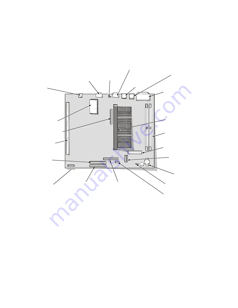
)LJXUH6\VWHP%RDUG&RPSRQHQWV
SEC cartridge connector
(SLOT1)
primary EIDE
interface connector
(IDE1)
diskette/tape drive
interface connector
(DSKT)
riser board
connector (RISER)
secondary EIDE
interface
connector (IDE2)
system
board
jumpers
battery socket
(BATTERY)
control panel
connector (PANEL)
3.3-V power input
connector (POWER_2)
main power input
connector (POWER_1)
DIMM sockets (2)
(DIMM_A–DIMM_B)
front of computer
ATI multimedia
channel connector (AMC)
video-memory
upgrade socket
(VIDEO_UPGRADE)
optional NIC
connector
(ENET)
video connector
(MONITOR)
microprocessor
fan connector
(FAN)
serial port 2
connector (SERIAL2)
USB connectors (2)
(USB)
parallel/serial port 1
connectors (stacked)
(PARALLEL/SERIAL1)
mouse/keyboard
connectors (stacked)
(MOUSE/KYBD)
chassis-intrusion switch
connector (INTRUSION)
Содержание OptiPlex G1
Страница 1: ...ZZZ GHOO FRP HOO 2SWL3OH 0DQDJHG 3 6 VWHPV 6 59 0 18 ...
Страница 35: ...System Overview 1 25 LJXUH 3RZHU DEOHV IRU WKH 0LGVL H DQG 0LQL 7RZHU RPSXWHUV P7 P9 P5 P4 P3 P2 P1 P6 ...
Страница 44: ...1 34 Dell OptiPlex G1 Managed PC Systems Service Manual ...
Страница 58: ...3 8 Dell OptiPlex G1 Managed PC Systems Service Manual ...
Страница 82: ...4 24 Dell OptiPlex G1 Managed PC Systems Service Manual ...
Страница 132: ...6 26 Dell OptiPlex G1 Managed PC Systems Service Manual ...
Страница 143: ......
Страница 144: ... ZZZ GHOO FRP 3ULQWHG LQ 0DOD VLD 3 1 ...


