1-14
Dell OptiPlex G1 Managed PC Systems Service Manual
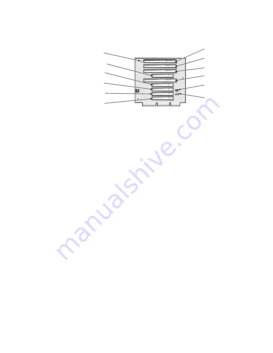
The mini tower riser board includes the P1 connector (for connecting the NIC
to the riser board cable) and an LED. If the LED is on, the riser board is receiv-
ing power; if off, the riser board is not receiving power.
)LJXUH5LVHU%RDUGIRUWKH0LQL7RZHU&RPSXWHU
8SJUDGH2SWLRQV
The system board can accommodate the following system upgrades:
Microprocessor upgrade
Main memory expansion
Video memory expansion
These upgrades are summarized in the following subsections, and installation
procedures are provided for the various chassis configurations in Chapters 4, 5,
and 6.
0LFURSURFHVVRU/&DFKH8SJUDGHV
The microprocessor and secondary L2 cache memory are implemented in an
SEC cartridge/heat sink assembly. Upgrade to a higher-performance micro-
processor is accomplished by snapping out the old assembly and installing an
upgrade assembly as higher-performance microprocessors become available.
0DLQ0HPRU\([SDQVLRQ
The two DIMM sockets on the system board can accommodate combinations
of 32-, 64-, and 128-MB, 64-bit nonparity DIMMs, up to a total memory capac-
ity of 256 MB.
ISA4
ISA1
HDLED
connector
P1 connector
PCI1
PCI5
ISA2
PCI2
PCI3
ISA3
LED
PCI4
Содержание OptiPlex G1
Страница 1: ...ZZZ GHOO FRP HOO 2SWL3OH 0DQDJHG 3 6 VWHPV 6 59 0 18 ...
Страница 35: ...System Overview 1 25 LJXUH 3RZHU DEOHV IRU WKH 0LGVL H DQG 0LQL 7RZHU RPSXWHUV P7 P9 P5 P4 P3 P2 P1 P6 ...
Страница 44: ...1 34 Dell OptiPlex G1 Managed PC Systems Service Manual ...
Страница 58: ...3 8 Dell OptiPlex G1 Managed PC Systems Service Manual ...
Страница 82: ...4 24 Dell OptiPlex G1 Managed PC Systems Service Manual ...
Страница 132: ...6 26 Dell OptiPlex G1 Managed PC Systems Service Manual ...
Страница 143: ......
Страница 144: ... ZZZ GHOO FRP 3ULQWHG LQ 0DOD VLD 3 1 ...


