64
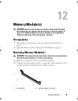
Memory Module(s)
Replacing Memory Module(s)
CAUTION:
If the memory module is not installed correctly, your computer may not
boot.
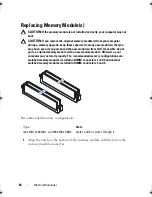
CAUTION:
If you remove the original memory module(s) from your computer
during a memory upgrade, keep them separate from any new module(s) that you
may have, even if you purchased the new module(s) from Dell. If possible, do not
pair an original memory module with a new memory module. Otherwise, your
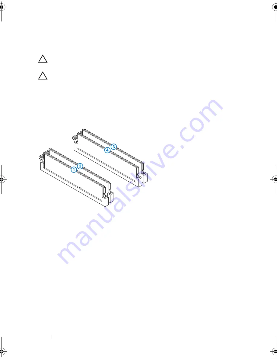
computer may not start properly. The recommended memory configurations are:
matched memory modules installed in DIMM connectors 1 and 2 and another
matched memory modules installed in DIMM connectors 3 and 4.
Recommended memory configuration:
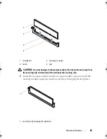
1
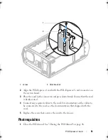
Align the notch on the bottom of the memory module with the tab on the
memory-module connector.
Type
Slots
1333 MHz,1600 MHz, and 1866 MHz DDR3
Slots 1 and 2 or slots 1 through 4
book.book Page 64 Wednesday, May 16, 2012 2:37 PM
Содержание Alienware Aurora R4
Страница 16: ...16 Before you Begin ...
Страница 24: ...24 Technical Overview ...
Страница 26: ...26 Left Side Panel 1 release panel 2 security cable slot 3 security cable slot latch 4 left side panel 1 2 3 4 ...
Страница 28: ...28 Left Side Panel ...
Страница 31: ...Hard Drive s 31 2 Follow the steps in After Working Inside Your Computer on page 15 ...
Страница 32: ...32 Hard Drive s ...
Страница 36: ...36 Hard Drive Fan Assembly ...
Страница 39: ...Optical Drive s 39 2 Follow the steps in After Working Inside Your Computer on page 15 ...
Страница 40: ...40 Optical Drive s ...
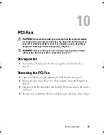
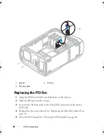
Страница 56: ...56 PCI Fan Assembly ...
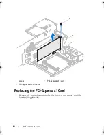
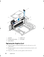
Страница 62: ...62 Graphics Card ...
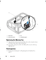
Страница 69: ...Memory Fan 69 2 Follow the steps in After Working Inside Your Computer on page 15 ...
Страница 70: ...70 Memory Fan ...
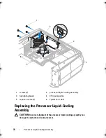
Страница 74: ...74 Processor Liquid Cooling Assembly ...
Страница 81: ...Processor 81 ...
Страница 82: ...82 Processor ...
Страница 88: ...88 Power Supply ...
Страница 92: ...92 Coin Cell Battery ...
Страница 98: ...98 System Board Assembly ...
Страница 102: ...102 Master I O Board ...
Страница 106: ...106 Top Lighting Board ...
Страница 108: ...108 Right Side Top Panel 2 Remove the screw that secures the right side top panel ...
Страница 112: ...112 Right Side Top Panel ...
Страница 116: ...116 Right Side Middle Panel ...
Страница 120: ...120 Right Lighting Board ...
Страница 122: ...122 Right Side Bottom Panel 2 Slide and remove the right side bottom panel from the chassis 1 screws 2 1 ...
Страница 135: ...Back Bezel 135 1 screws 2 2 back bezel 3 tabs 1 2 3 ...
Страница 140: ...140 WiFi Bluetooth Assembly ...
Страница 144: ...144 Top I O Panel ...
Страница 158: ...158 System Setup Utility ...
Страница 160: ...160 Flashing the BIOS 8 Double click the file icon on the desktop and follow the instructions on the screen ...
Страница 162: ...162 Specifications ...