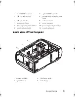

Technical Overview
21
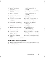
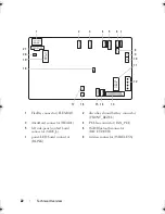
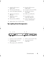
Master I/O Board Components
NOTE:
The location of the connectors may vary based on the selections you made
at the time of purchase.
1
heat-sink fan connector
(SYS_FAN1)
2
memory-module connector
(DIMM1)
3
memory-module connector
(DIMM2)
4
processor power connector (PWR2)
5
processor socket (CPU1)
6
memory-module connector
(DIMM4)
7
memory-module connector
(DIMM3)
8
processor fan connector
(CPU_FAN)
9
main power connector (PWR1)
10
front USB connector (FUSB3_0)
11
heat-sink fan connector
(SYS_FAN2)
12
battery socket (BAT1)
13
CMOS jumper (CLEAR_CMOS)
14
serial ATA drive connectors
(SATA1_2)
15
serial ATA drive connectors
(SATA3_4)
16
serial ATA drive connectors
(SATA5_6)
17
password jumper (PASSWORD)
18
front panel connector
(FRONT_PANEL)
19
USB connector (USB1)
20
USB connector (USB2)
21
USB connector (USB3)
22
Low pin count debug header (LPC)
23
front audio connector
(FRONT_AUDIO)
24
PCI-Express x1 connector (SLOT4)
25
PCI-Express x16 connector
(SLOT3)
26
PCI-Express x1 connector (SLOT2)
27
PCI-Express x16 connector (SLOT1)
book.book Page 21 Wednesday, May 16, 2012 2:37 PM
Содержание Alienware Aurora R4
Страница 16: ...16 Before you Begin ...
Страница 24: ...24 Technical Overview ...
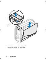
Страница 26: ...26 Left Side Panel 1 release panel 2 security cable slot 3 security cable slot latch 4 left side panel 1 2 3 4 ...
Страница 28: ...28 Left Side Panel ...
Страница 31: ...Hard Drive s 31 2 Follow the steps in After Working Inside Your Computer on page 15 ...
Страница 32: ...32 Hard Drive s ...
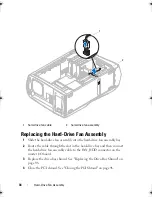
Страница 36: ...36 Hard Drive Fan Assembly ...
Страница 39: ...Optical Drive s 39 2 Follow the steps in After Working Inside Your Computer on page 15 ...
Страница 40: ...40 Optical Drive s ...
Страница 56: ...56 PCI Fan Assembly ...
Страница 62: ...62 Graphics Card ...
Страница 69: ...Memory Fan 69 2 Follow the steps in After Working Inside Your Computer on page 15 ...
Страница 70: ...70 Memory Fan ...
Страница 74: ...74 Processor Liquid Cooling Assembly ...
Страница 81: ...Processor 81 ...
Страница 82: ...82 Processor ...
Страница 88: ...88 Power Supply ...
Страница 92: ...92 Coin Cell Battery ...
Страница 98: ...98 System Board Assembly ...
Страница 102: ...102 Master I O Board ...
Страница 106: ...106 Top Lighting Board ...
Страница 108: ...108 Right Side Top Panel 2 Remove the screw that secures the right side top panel ...
Страница 112: ...112 Right Side Top Panel ...
Страница 116: ...116 Right Side Middle Panel ...
Страница 120: ...120 Right Lighting Board ...
Страница 122: ...122 Right Side Bottom Panel 2 Slide and remove the right side bottom panel from the chassis 1 screws 2 1 ...
Страница 135: ...Back Bezel 135 1 screws 2 2 back bezel 3 tabs 1 2 3 ...
Страница 140: ...140 WiFi Bluetooth Assembly ...
Страница 144: ...144 Top I O Panel ...
Страница 158: ...158 System Setup Utility ...
Страница 160: ...160 Flashing the BIOS 8 Double click the file icon on the desktop and follow the instructions on the screen ...
Страница 162: ...162 Specifications ...