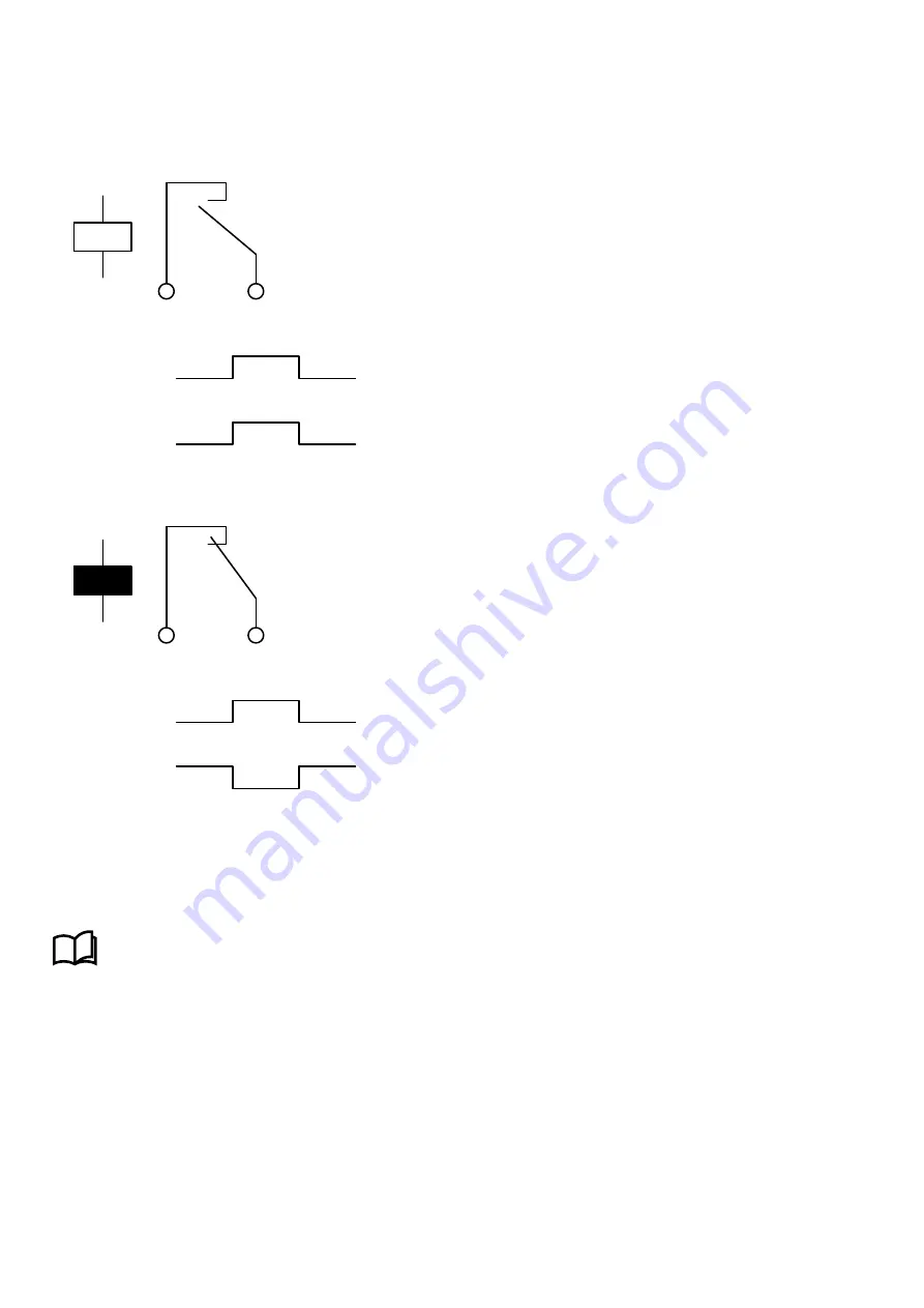
Configured state
You can configure the normal transistor state in software in the display unit or PICUS. Under
Configure > Input/output
, select the
terminals, then select
Normally de-energised
(the default) or
Normally energised
for the
Coil state
.
Table 13.27
Transistor, configured in software as normally de-energised
NO
Function
Transistor
(1)
(2)
Normally
de-energised
1.
Function
: The digital output function assigned to the terminals. The
controller software activates the function. For example:
Breakers > [Breaker]
> Command > [*B] Close
.
2.
Transistor
: The controller closes the transistor when the function is
activated.
Table 13.28
Transistor, configured in software as normally energised
NO
Function
Transistor
(1)
(2)
Normally
energised
1.
Function
: The digital output function assigned to the terminals. The
controller software activates the function. For example:
Breakers > [Breaker]
> Command > [*B] Close
.
2.
Transistor
: The controller opens the transistor when the function is
activated.
13.8.4 Digital input characteristics
IOM3.4 has two groups of digital inputs. The first group is terminals 15 to 22, with a common on terminal 23. The second group is
terminals 24 to 31, with a common on terminal 32. The groups are not connected to each other.
More information
See
Hardware characteristics and configuration
,
General characteristics
,
Digital input characteristics and
configuration
for more information.
13.9 Engine interface module EIM3.1
13.9.1 Engine interface module EIM3.1
The engine interface module has its own power supply and a tacho input to measure speed. It also has four relay outputs, four
digital inputs, and three analogue inputs. These I/Os are configurable.
The power supply terminals include circuit protection against load dump transients and JEM177 surge transients (rugged design).
DESIGNER'S HANDBOOK 4189340911K UK
Page 443 of 521


