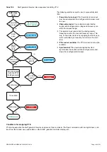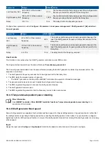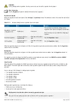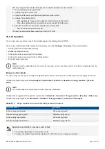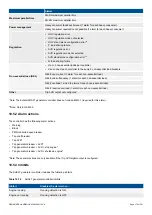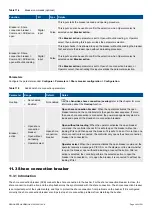
Functions
◦
Power export (active and reactive) (to the shore connection)
◦
Power import (active and reactive) (to the ship busbar)
Control types
•
Power management system (PMS) control
◦
Display unit push-buttons for breaker operations
◦
Synchronisation, de-loading, and breaker control
◦
Push-button functions also possible using inputs, PICUS, and/or Modbus
•
Switchboard control
◦
Operator controls the system from the switchboard
◦
Only the controller protections are active
Redundancy
•
Redundant breaker feedback on externally controlled shore connection breakers
11.2 SHORE connection controller principles
11.2.1 Adding a SHORE connection controller to the single-line diagram
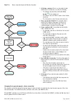
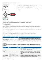
Configure each SHORE connection controller in the single-line diagram, using PICUS.
To add a SHORE connection controller to the single-line diagram:
1. In PICUS, under
Configure > Single-line
, drag the
shore connection icon
to the right place on the
single-line diagram.
2. Select the SHORE connection controller on the single-line diagram, and make sure that its
Controller
ID
is correct.
3. Broadcast the changes to all the controllers in the system.
•
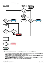
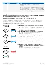
If needed you can override the controller ready status.
11.2.2 Nominal settings
Shore busbar nominal settings
These nominal settings are found under
Configure > Parameters > Shore connection > Nominal settings > Nominal settings #
,
where # is 1 to 4.
Table 11.1
Controller nominal settings
Nominal setting
Range
Default
Notes
Voltage (V)
10 V to 160 kV
400 V
The phase-to-phase nominal voltage for the shore connection.
Current (I)
1 A to 9 kA
867 A
The maximum current from the shore connection during normal operation.
Frequency (f)
48 to 62 Hz
50 Hz
The system nominal frequency. All the controllers in the system should have
the same nominal frequency.
Power (P)
1 kW to 900 MW 480 kW
Configure the value according to the shore connection. Set the value to ensure
the shore connection over-power alarm is triggered at the correct time.
Apparent power (S) 1 kVA to 1 GVA
530 kVA Shore connection apparent power.
Power factor (PF)
0.6 to 1
0.9
Shore connection power factor.
The controller uses the nominal settings to calculate the nominal reactive power (nominal Q) for the shore connection. The controller
can be configured to calculate the nominal active power (nominal P) or the nominal apparent power (nominal S). In this case, the
controller uses the calculated values, and ignores any entered values.
DESIGNER'S HANDBOOK 4189340911K UK
Page 378 of 521

