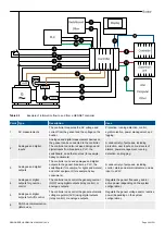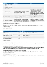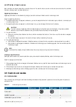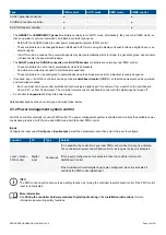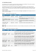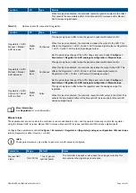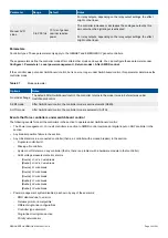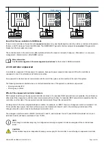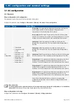
Table 2.2
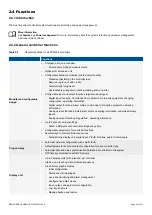
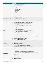
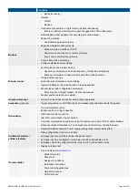
Example of information flow to and from a GENSET controller
Point Type
Description
Uses
1
AC measurements
The controller measures the AC voltage and
current from the genset and the voltage on the
busbar.
Protection, running detection, control,
synchronisation, power management, and
logging.
2
Analogue and digital
inputs
Analogue and digital measurement devices on
the genset can be connected to the controller.
The controller can also receive analogue and
digital inputs from breakers, a PLC, the
switchboard, and other sources (for example,
heavy consumers).
A wide variety of purposes, including
protection, user inputs, various levels of
alarms, power management, running
detection, and logging.
3
Analogue and digital
outputs
The controller can send analogue and digital
outputs to the genset, breakers, a PLC, the
switchboard (for example, for lights and meters),
and other equipment (for example, heavy
consumers).
A wide variety of purposes, including
control, status and alarm indicators, and as
input to a PLC.
4
Analogue or digital
outputs for governor
control
The controller can control the genset governor
(GOV) using digital outputs (relay control), or
analogue outputs.
Regulate the genset frequency, and/or
active power (depending on the system
configuration).
5
Analogue or digital
outputs for AVR control
The controller can control the genset automatic
voltage regulator (AVR) using digital outputs
(relay control), or analogue outputs.
Regulate the genset voltage and/or reactive
power (depending on the system
configuration).
6
CAN bus communication
(future use)
DESIGNER'S HANDBOOK 4189340911K UK
Page 29 of 521


