background image

7

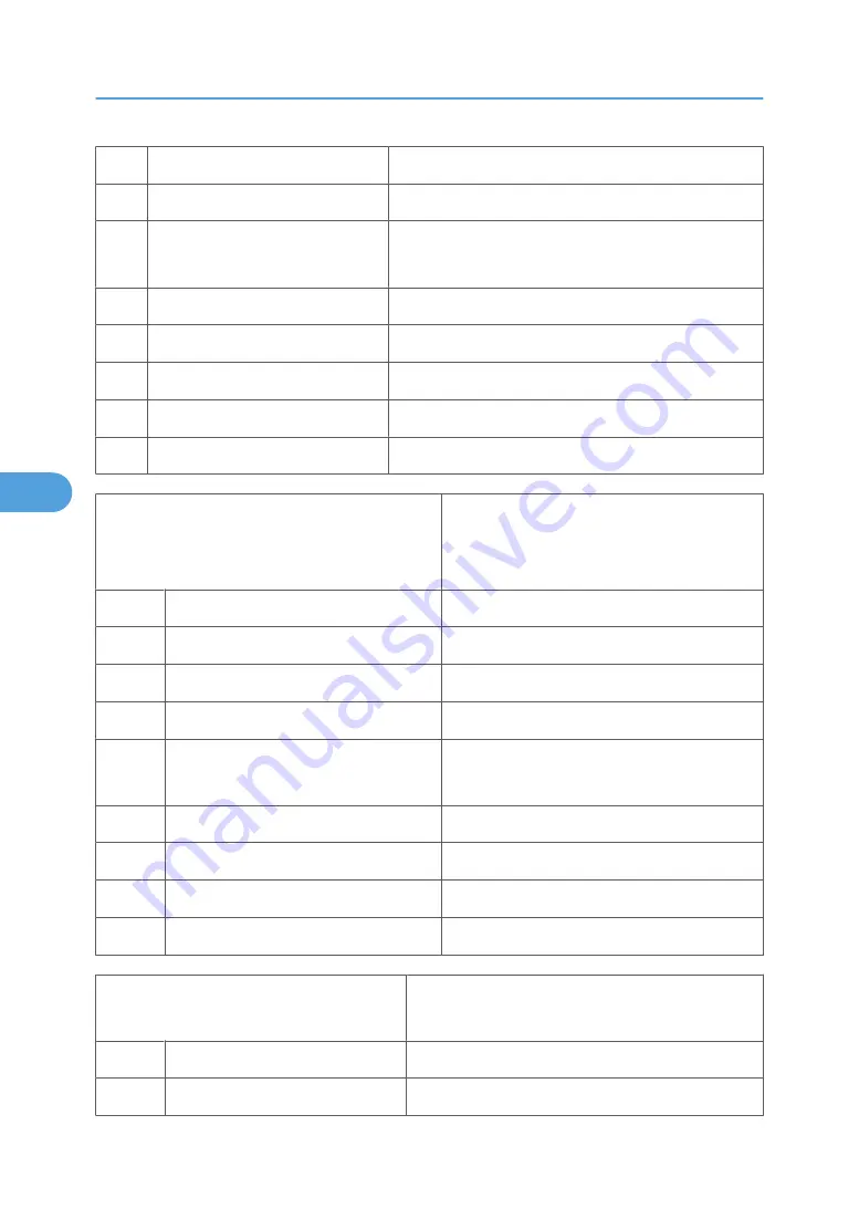
Detect dial tone before dialing

0:Disable, 1:Enable

6

PSTN/PBX setting

0:PSTN, 1:PBX (select PBX line type)

5

PBX Dial Tone Detect

0: No detection of tone before PBX prefix
1: Detects tone before PBX prefix

4

Dial mode select

0:DTMF-PB, 1:Pulse-DP

3

Reserved

2

Reserved

1

Reserved

0

Reserved

Bit SW03

• Send tone 1400 Hz 3 sec in fax/tel mode
• Force user to register fax no./user name
• TSI/CSI append "+"

Bit

Name

Function

7

Send tone 1400 Hz 3 sec in fax/tel mode 0:Disable, 1:Enable

6

Reserved

5

Force user to register fax no./user name 0:Disable, 1:Enable

4

TSI/CSI append "+"

0: Do not append "+" before TSI/CSI
1: Append "+" automatically

3

Reserved

2

Reserved

1

Reserved

0

Reserved

Bit SW04

• Dial registered limit for tel. no.
• Visible alarm for RTN (Return To Negative) signal

Bit

Name

Function

7

Dial registered limit for tel no.

0: 50 digits, 1: 40 digits

5. Service Tables

216

5

Содержание J012

Страница 1: ...Toscana C1a C1b C1bN Machine Code J012 J013 J014 SERVICE MANUAL July 2007 Subject to change ...

Страница 2: ...e completed service training for the machine and all optional devices designed for use with the machine Installation The main machine and options can be installed by either the customer or customer engineer The customer or customer engineer must follow the installation instructions described in the operating instructions Reference Material for Maintenance Maintenance shall be done with the special...

Страница 3: ...evices To prevent electrical shock switch the machine off wait for a few seconds and then unplug the machine from the power source Before you do any checks or adjustments after turning the machine off work carefully to avoid injury After removing covers or opening the machine to do checks or adjustments avoid touching electrical components or moving parts gears timing belts etc After turning the m...

Страница 4: ...diately Never do any procedure that defeats the function of any safety device Modification or removal of a safety device fuse thermistor etc could cause a fire and personal injury After removal and replacementofanysafetydevice alwaystesttheoperationofthemachinetoensurethatitisoperating normally and safely For replacement parts use only the correct fuses thermistors circuit breakers etc rated for u...

Страница 5: ...her damage Replace the power cord if necessary A frayed or otherwise damaged power cord can cause a short circuit which could lead to a fire or personal injury from electrical shock Check the length of the power cord between the machine and power supply Make sure the power cord is not coiled or wrapped around any object such as a table leg Coiling the power cord can cause excessive heat to build u...

Страница 6: ...rators have read and understand all the safety instructions described in the operating instructions Demonstrate how to turn off the power and disconnect the power plug by pulling the plug not the cord if any of the following events occur 1 Something has spilled into the product 2 Service or repair of the product is necessary 3 The product cover has been damaged Caution operators about removing pap...

Страница 7: ...al Attach the caps to empty ink containers for temporary storage to avoid accidental spillage Return empty ink cartridges to a local dealer who can accept such items for collection and recycling or disposal If the customer decides to dispose of empty ink cartridges make sure that they are disposed of in accordance with local laws and regulations Safety Instructions for This Machine Introduction Th...

Страница 8: ... it can be un plugged easily Disconnect the power plug by pulling the plug not the cable if the power cable or plug becomes frayed or otherwise damaged The supplied power cord is for use with this equipment only Do not use with other appliances Doing so may result in fire electric shock or injury Connect the machine only to the power source described on the inside front cover of this manual Connec...

Страница 9: ... there is a continuous air turnover Unplug the power cord from the wall outlet before you move the machine While moving the machine you should take care that the power cord will not be damaged under the machine Before moving the machine be sure to disconnect all external connections especially the power cord from the wall outlet Damaged power cords are a fire and electric shock hazard When the mac...

Страница 10: ... a doctor if you have a problem Avoid getting ink on your clothes or skin when removing a paper jam or replacing ink cartridges If your skin comes into contact with ink wash the affected area thoroughly with soap and water If ink gets on your clothing wash with cold water Hot water will set the ink into stain impossible Keep the ink or ink container out of reach of children Do not look into the la...

Страница 11: ...you to handle it carefully to avoid ink spillage User Information on Electrical Electronic Equipment Users in the EU Switzerland and Norway Our Products contain high quality components and are designed to facilitate recycling Our products or product packaging are marked with the symbol below 10 ...

Страница 12: ...u purchased it your local dealer or sales service representatives All Other Users If you wish to discard this product please contact your local authorities the shop where you bought this product your local dealer or sales service representatives International ENERGY STAR Office Equipment Program The International ENERGY STAR Office Equipment Program encourages energy conservation by promoting ener...

Страница 13: ... battery with the incorrect type could cause the battery to explode If there is a problem with a circuit board replace the entire board as a single unit Always obey the local laws and regulations regarding the disposal of used batteries PCBs and other electrical components 12 ...

Страница 14: ... options are available for the J012 J013 and J014 No Option Name For Machine J509 Paper Feed Unit TK2000 J012 J013 J014 J507 Multi Bypass Tray Type BY1000 J012 J013 J014 J510 Network Interface Board Type GX4 J012 J013 Standard for J014 The duplex unit attached to the back of the machine is standard for the J012 J013 J014 and must always remain installed for the machines to operate properly The dup...

Страница 15: ...machine or Press either the up or down arrow on the scroll key or Press either the left or right arrow on the scroll key Example Machine operation panel procedures are abbreviated to reduce the needless repetition of words and make procedures easier to read What You See What This Means 1 Menu 1 Press the Menu key 2 or System Settings Yes 2 Press either the or key to display System Settings then pr...

Страница 16: ...ols in section 3 Replacement and Adjustment Symbol What It Means Screw Connector E ring Clip ring Clamp This manual uses SEF Short Edge Feed and LEF Long Edge Feed to denote paper orientation Warnings Cautions Notes In this manual the following important symbols and notations are used A Warning indicates a potentially hazardous situation Failure to obey a Warning could result in death or serious i...

Страница 17: ...marks Microsoft Windows Windows Server and VistaTM are registered trademarks of Microsoft Corporation in the United States and or other countries PostScript is a registered trademark of Adobe Systems Incorporated PCL is a registered trademark of Hewlett Packard Company Ethernet is a registered trademark of Xerox Corporation PowerPC is a registered trademark of International Business Machines Corpo...

Страница 18: ...and Abbreviations 15 Warnings Cautions Notes 15 Trademarks 16 1 Installation Preparation 25 Environment 25 Choosing a Location 25 Minimum Space Requirements 26 Power Source 27 Computer Hardware and Software 27 Using the Operation Panel 29 Summary of Important Operation Panel Keys 29 Entering Text 31 Quick Summary of Important Procedures 33 Installation Procedure 36 What You Need 36 Accessory Check...

Страница 19: ...ble 63 Service Call Procedures 63 Regular Cleaning 64 3 Replacement and Adjustment Before Replacing Parts 65 Removal Table 65 Important Notice 68 Procedure Summary 69 Common Procedures 73 Network Interface Board NIB 73 Duplex Unit 73 Ink Collector Unit 74 Platen J012 only 76 ADF J013 J014 76 Original Pressure Plate 77 Scanner to Full Upright 78 Paper Cassette Output Tray 79 Right Front Cover 80 Ri...

Страница 20: ...ance Unit Motor 112 Rear Fan 114 Front Fan 115 Sensors 116 Vertical Encoder Sensor 116 Carriage Position Sensor 117 Ink Level Sensor 118 1st Registration Sensor 119 2nd Registration Sensor 120 Scanner Unit Sensor 122 Air Release Solenoid 123 Cleaning Procedures 124 Flushing Gate Cleaning 125 Maintenance Unit Cleaning 125 Feed Roller Cleaning 127 Transport Belt Cleaning 128 Friction Pad Cleaning 12...

Страница 21: ...lf Diagnostic Test Flow 157 SC Error Codes 160 Summary of Error Levels 160 Out of Range Temperature Errors 160 SC Code Tables 161 Jam Codes 164 Facsimile Errors 172 Image Correction 179 Preparing for Test Printing 179 Nozzle Check 179 Print Head Cleaning 180 Print Head Flushing 181 Adjust Paper Feed 181 Head Position 183 Registration 184 Drive Cleaning 186 Cleaning the Printheads Before Storage 18...

Страница 22: ...roup 7000 256 Bit Switches 270 Changing Bit Switch Settings 270 Bit Switch Summary 270 6 Detailed Section Descriptions Important Parts 275 J012 275 J013 J014 278 Boards 281 Board Circuit Diagram 281 Board Layout Diagram 282 Electrical Components 283 Overview 283 Electrical Component Summary 288 Print Heads 296 Overview 296 Print Head 296 Print Head Tank 297 Ink Ejection Device 298 Ink Near End 299...

Страница 23: ... Unit 311 Print Head Maintenance Cycles 316 Ink Collector Tank 317 Ink Collector Ink level sensor 318 Flushing Unit 319 Carriage Drive 320 Overview 320 Envelope Selector 321 Paper Feed Transport Paper Exit 322 Overview 322 Cassette Lock Release 323 Leading Edge and Paper Size Detection 323 Paper Jam Trailing Edge Detection 324 Paper Transport Drive 324 Paper Path 325 Transport Belt 326 Charge Leak...

Страница 24: ...s Tray Option 334 Paper Feed Unit Option 336 Overview 336 Paper Feed 337 ADF 338 Overview 338 Drive 338 7 Specifications General Specifications 341 ADF 341 Scanner 341 General Specifications 342 ADF 346 Target Yields 346 Environment 348 Operation Specifications 349 Options 355 Paper Size Table 357 Controller 360 Interface Specifications 361 Supported Utilities 362 23 ...

Страница 25: ...24 ...

Страница 26: ...to 89 6 F Humidity Range 15 to 80 RH Ambient Illumination Less than 1 500 Lux never expose to direct sunlight Ventilation More than 30 m3 hr person in the work area Ambient Dust Less than 0 10 mg m3 Choosing a Location 1 Always install the machine On a sturdy level surface Where it will not be exposed to either very low or very high humidity 25 1 ...

Страница 27: ...hine at any location higher than 2 000 m 6 500 ft above sea level 5 Set up and use the machine on a sturdy level surface Place a carpenter s level on the machine front to back and side to side and confirm that it is level Variations between the front back and left right level readings should be less than 2 degrees Minimum Space Requirements No Minimum Clearance Comments 1 120 mm 4 8 in Without Mul...

Страница 28: ...3 Windows NT 4 0 or later HDD Toscana C1a J012 240 MB Toscana C1b J013 295 MB Toscana C1bN J014 300 MB For Windows NT 4 0 IE 4 0 or later is required Windows NT 4 0 does not support USB connection with this machine Connect the machine through a network connection The following operating systems support USB connection Windows 98 Windows Me Windows 2000 Windows XP Windows Server 2003 The following m...

Страница 29: ...mory Required Windows 2000 128 MB Windows XP 128 MB Windows Server 2003 256 MB Windows NT 4 0 64 MB This machine does not support operation with Windows XP 64 Bit Edition or Windows Server 2003 64 Bit Edition 1 Installation 28 1 ...

Страница 30: ...on The operation panel below is common for the J013 J014 and has all the fax keys on the left because both machines support the fax function Summary of Important Operation Panel Keys For a more detailed summary about the operation panel keys please refer to the User Guide Only the most important keys that may be required for servicing and maintenance are described below Using the Operation Panel 2...

Страница 31: ...tween Text Photo and Text Photo Text Text LED on For documents that contain only text Photo Photo LED on For photographs printed matter with photos magazines etc TextandPhoto BothLEDson Allowsthemachinetosetautomatically the optimum settings for an original that contains both text and photos 4 Data in Flashes while the machine is receiving a print job Lights and remains on when there is data in th...

Страница 32: ...of double sided originals 2 Sided Copy Duplex prints an original with pages printed on one side 14 Select Paper Tray Selects the paper feed source Tray 1 Tray 2 option Multi Bypass Tray option 15 Yes Press to enter an item selected from a menu or a value entered with the 10 key pad 16 No Cancels an operation or returns to the previous display in the menu mode 17 Resolution Toggles the resolution s...

Страница 33: ...n press the same number key again 3 To delete a number move or the cursor to the number to delete then press No This deletes the number at the cursor position 4 To enter a plus sign minus sign ampersand or slash press then to select the symbol that you want to enter To enter text The number keys are used to enter text Enter text with A on the operation panel display 5 If 1 is on the display press ...

Страница 34: ...eturn to standby mode if a key is not pressed for 60 sec To turn the machine on and off 1 To turn the machine on press and hold the Power key for at least 1 sec The Power LED lights and Please Wait appears on the operation panel display until the machine has warmed up When the machine is ready for operation the Power key LED lights and the Copy mode display appears 2 Press Power and hold for at le...

Страница 35: ...g the print heads always do a Nozzle Check to determine which color is not printing The print heads should be cleaned only if a problem exists To clean the print heads Do print head cleaning at least three times before you do head flushing Print a Nozzle Check to check the results of each cleaning 1 Pull the release under the operation panel forward and raise the scanner unit 2 Confirm that the en...

Страница 36: ...nt heads to be flushed All all print heads Print head 1 Black Cyan Print head 2 Magenta Yellow Yes Please Wait displays until flushing is finished Do not start any other operation until cleaning stops 7 Clear Modes Printhead cleaningandflushingbothconsumeink butflushingconsumesmoreinkthancleaning Flush the print head nozzles only if three cleanings do not solve the problem To feed 1 blank sheet pa...

Страница 37: ...Unit 1 4 Branding Plaque 1 3 5 Print cartridges 2 4 7 Power Cord 3 1 8 CD ROM Printer Driver HTML Manual 1 9 CD ROM Printer Driver HTML Manual EU languages 1 10 Quick Installation Procedure English 1 11 Quick Installation Procedure 10 Languages 1 12 Safety Information English 1 13 Safety Information 10 languages 1 14 Warranty Statement 1 15 User Registration Card 1 16 Help Desk Guide 1 17 Energy S...

Страница 38: ...nt Cartridge GC 21M J735 Print Cartridge GC 21C J734 Print Cartridge GC 21K 3 The power cord is attached to the NA model The power cord is provided as a separate item for the EU model only Remove the Shipping Material Before you do any of the procedures in this manual make sure the printer is turned off and unplugged from the power source Do not turn the printer on until you instructed to do so 1 ...

Страница 39: ...eight Machine Weight J012 20 kg 44 lb J013 23 kg 50 7 lb J014 23 5 kg 51 8 lb 2 Move the machine to the location where you want to install it To prevent damage to the printer always carry the printer as shown above 3 Remove all of the orange tape from the machine body 1 Installation 38 1 ...

Страница 40: ... 1 Front 2 Inside ADF 3 Under platen scanner unit 4 Under open scanner unit 5 Back of machine remove power cord Installation Procedure 39 1 ...

Страница 41: ... 6 Inside paper casette 7 Read instruction sheet and remove 4 Pull the scanner unit release lever 5 Lift the scanner unit 1 Installation 40 1 ...

Страница 42: ...e signs of irritation or other problems seek medical attention immediately Ifinkisswallowed drinkastrongsolutionofcoldwaterandtablesalttoinducevomiting Seekmedical attention immediately Ink is difficult to remove from fabric Work carefully to avoid staining clothing when performing routine maintenance or replacing cartridges Always store print cartridges out of the reach of children 1 Unpack the f...

Страница 43: ... order of insertion from left to right K Black C Cyan M Magenta Y Yellow 4 Insert the black print cartridge in the first slot on the left 5 Press on the area marked PUSH to insert the cartridge completely 6 Install the other print cartridges 7 Make sure that the four cartridges are inserted in this order from left to right K Black C Cyan M Magenta Y Yellow 8 Close the right front cover 1 Installat...

Страница 44: ...Load Paper 1 Raise the output tray 2 Pull the paper tray out of the machine Installation Procedure 43 1 ...

Страница 45: ...then slide the guides to a position slightly wider than the paper 4 Fan the stack to remove static cling 5 Load the stack with the print side face down 6 Make sure the top of the stack does not exceed the load limit mark 1 Installation 44 1 ...

Страница 46: ...e stack bows upward the fences are too tight 8 Adjust the side fence positions so the top of the stack is perfectly flat 9 Push the tray slowly into the printer until it stops 10 Lower the output tray Connect the Power Cord Always connect the printer to a correct power source Do not share the printer power source with another electrical device or appliance Installation Procedure 45 1 ...

Страница 47: ... 1 Press the Power key The printer starts pumping ink into the ink tanks Two alternating messages are displayed with a progress bar to keep you informed about the progress of ink filling Filling the ink tanks requires about 6 to 10 minutes Do not use the printer or touch any key on the operation panel until you see the Ready message on the operation panel display As soon as the Ready message is di...

Страница 48: ...language Yes Please Re start Power Off On 6 Cycle the machine off on to set the language for the menu displays Set Paper Type and Size for Tray 1 1 Menu System Settings 2 or Tray Paper Setting Yes Tray1 3 Yes Paper Type Yes Plain Paper 4 or Select the type of paper that will be loaded in Tray 1 5 Yes Tray Paper Setting Yes Tray1 Yes Paper Type 6 or Paper Size Yes 7 or Select the size of paper that...

Страница 49: ...Yes Please Wait displays as the report prints 5 Clear Modes Standby 6 Check the settings Install USB and Printer Driver Connect the USB Cable 1 If the machine is on switch it off 2 Turn the computer on and start Windows 3 Remove the seal from the USB slot on the back of the machine 4 Insert the Type B plug hexagonal of the USB cable into the slot 5 Insert the other plug of the USB cable Type A Fla...

Страница 50: ... click Cancel and make sure that the machine power is off 6 Select an language for the interface and click OK 7 Click Quick Install for USB 8 Read the license agreement then click I accept the agreement Next 9 Confirm that the machine power is off then click Next You are prom pted to once again confirm that the machine power is off 10 Make sure the machine power is off then click Next You should s...

Страница 51: ...n click Browse 3 Browse to find DRIVERS on the CD ROM then click OK 4 Select the folder for your operating system 5 Clear the Search remove media checkbox The Drivers Manual Utilities dialog box should appear after the CD ROM is inserted If it does not appear open Explorer or the Control Panel double click the CD ROM icon and then double click Setup exe to start the installation The User Guide ico...

Страница 52: ...st be prepared and set up before the machine is placed on top of the unit Two people are required to lift the machine and place it on top of the Paper Feed Unit PFU Machine Weight Machine Weight Toscana C1a 20 kg 44 lb Toscana C1b 23 kg 50 7 lb Toscana C1bN 23 5 kg 51 8 lb 1 Make sure that the machine power cord is not connected to the power source 2 Remove the paper feed unit PFU from its box 3 R...

Страница 53: ...he bottom of the machine with the pegs of the paper tray while you hold the machine as shown 8 Slowly set the machine on top of the PFU Load Paper in the Paper Feed Unit 1 Raise the paper tray slightly and pull it toward you to remove it 2 Remove the paper tray cover 3 Pinch the tabs of the bottom fence then slide it completely forward 4 Fan a stack of paper to remove static cling 1 Installation 5...

Страница 54: ...ize Settings for Tray 2 1 Menu System Settings 2 or Tray Paper Setting Yes Tray1 3 or Tray2 Yes Paper Type Yes Plain Paper 4 or Select the type of paper that will be loaded in Tray 2 5 Yes Tray Paper Setting Yes Tray2 Yes Paper Type 6 or Paper Size Yes 7 or Select the size of paper that will be loaded in Tray 2 8 Yes Tray Paper Setting 9 Clear Modes Standby 10 Cycle the machine off on Multi Bypass...

Страница 55: ...g duplex printing Set Paper Type and Size for the Multi Bypass Tray Do the Paper Type Size Setting for the Multi Bypass Tray 1 Menu System Settings 2 or Tray Paper Setting Yes Tray1 3 or Bypass Tray 4 Yes Paper Type Yes Plain Paper 5 or Select the type of paper that will be loaded the Multi Bypass Tray 6 Yes Tray Paper Setting Yes Tray1 7 or Bypass Tray 8 or Paper Size Yes 9 or Select the size of ...

Страница 56: ...to the J014 so the installation procedure described below is not necessary for the J014 However the Network Interface Board J510 is an option for the J012 J013 and must be installed 2 Make sure that the machine is switched off and disconnected from its power source 3 Lift the connector cover 4 Before you touch the network interface board touch a metal surface to ground any static charge Handle the...

Страница 57: ... how to connect the Ethernet cable and do the network settings see the Quick Installation Guide Connect the NIB Be sure to install the necessary network equipment a hub for example before connecting the Ethernet cable to the machine An Ethernet cable is not provided with the machine Select a proper cable for the network environment 1 Plug the Ethernet cable into the Ethernet port of the machine 1 ...

Страница 58: ...s procedure ask the network administrator for the IP address 1 If the machine is off press Power to switch it on 2 Menu System Settings 3 or Network Settings Yes These are the settings on the Network Settings menu Setting Default 1 Machn IP Address Auto 2 Subnet Mask 0 0 0 0 3 Gateway Address 0 0 0 0 4 DNS Settings Inactive 5 Ethernet Speed Auto 6 Reset Ethernt Bd 1 or 1 Machn IP Adress Yes 2 or S...

Страница 59: ...ttings for 2 Subnet Mask and 3 Gateway Address 6 Do the settings for 4 DNS Settings and 5 Transfer Speed if these settings are required Please Re start Power Off On 7 Power Cycle the machine off on to save the settings 1 Installation 58 1 ...

Страница 60: ...ord Tape the power cord to the back of the machine Remove all paper in the feed trays Do a test print to confirm that the machine operates correctly after you move it to another location Do the print head cleaning procedures with the machine driver if necessary The print cartridges should remain in the machine It is not necessary to remove them before transporting the machine To avoid ink spillage...

Страница 61: ...leaning 5 Do print head flushing if three consecutive cleanings do not solve the problem 6 If flushing does not solve the problem allow the printer to sit idle for about 10 minutes then print another Nozzle Check 7 If the Nozzle Check print is still not satisfactory allow the printer to sit idle for at least 8 hours and then print another Nozzle Check Moving the Printer 1 Switch the printer off 2 ...

Страница 62: ...e grooves on the sides of the machine Hold the machine level Never allow it to tilt more than 45 from horizontal 6 Carry it slowly and avoid tilting the machine 7 If the machine is being moved a long distance pack it in its original box Be sure to unlock the shipping lock after the machine arrives at its new location Important Information 61 1 ...

Страница 63: ...1 Installation 62 1 ...

Страница 64: ...hen you replace the waste ink tank To remove hardened ink you may need to use a small screwdriver or similar tool Friction Pad Damp cloth This is the cork friction pad on the front edge of the standard paper cassette Maintenance Unit Dry cloth Always use a tightly wrapped dry cloth to remove the ink that has hardened around the suction cap and wiper blade when you replace the waste ink tank Printe...

Страница 65: ...r Cleaning The following items should be cleaned regularly Exposure glass Á Scanning glass White plate Note Avoid bending the exposed edges of the mylars Platen background plate 2 Preventive Maintenance 64 2 ...

Страница 66: ... Friction Pad 3 Duplex Unit Installed on back of machine 4 End Fence Inside paper cassette 5 End Fence Inside PFU 6 Firmware Update Through USB Connection 7 Ink Cartridge 8 Ink Collector Unit 9 Ink Tank Cover Top 10 Key Switch Panel Operation Panel 11 NIB Cover Protects inserted NIB 12 Operation Panel Fax Seal 14 Original Cover 16 Paper Cassette Standard 17 Paper Cassette PFU Option 18 Paper Outpu...

Страница 67: ...asy 5 ARDF Pickup Roller J013 J014 Easy 6 ARDF Right Hinge J013 J014 Easy 7 ARDF Unit Easy 8 ARDF Unit J013 J014 Easy 9 Air Release Solenoid Easy 10 Carriage Position Sensor Easy 11 Carriage Unit Easy 12 Controller Board J012 Easy 13 Controller Board J013 Easy 14 Controller Board J014 Easy 15 Cooling Fan Difficult 16 Cover Rear Easy 17 Covers Front Left Right Easy 18 Duplex Unit Detection Board Di...

Страница 68: ... Scanner Unit J014 NA Difficult 34 Scanner Unit Hinges Left Right 35 Transport Belt Easy 36 Vertical Encoder Sensor Easy 37 Vertical Encoder Wheel Easy 38 Vertical Motor Easy Easy These procedures require setting the scanner unit in the full upright position Removal of left right and front cover may be required Removal of the scanner unit and back cover are not required Difficult Removal of all co...

Страница 69: ... Ink Supply Pump Unit 3 Transport Belt 4 Charge Roller 5 Temperature Humidity Sensor 6 Paper End Sensor 7 Paper Feed Roller Important Notice During parts removal never remove any of the screws shown below 3 Replacement and Adjustment 68 3 ...

Страница 70: ...rrectly aligned If these screws are loosened or removed this could throw the carriage mechanism out of alignment Procedure Summary The reference table below is a list of components in alphabetic order The left column lists the item to be removed Before Replacing Parts 69 3 ...

Страница 71: ...ay 4 Right Cover 5 Left Cover 6 Scanner Unit 7 Rear Cover ADF J013 J014 Air Release Solenoid 1 Platen or ADF 2 Scanner Unit to Upright 3 Paper Cassette Output Tray 4 Right Cover CTL Board NVRAM 1 Platen or ADF 2 Scanner to Full Upright 3 Paper Cassette Output Tray 4 Right Cover 5 Left Cover 6 Scanner Unit 7 Rear Cover Carriage Position Sensor 1 Platen or ADF 2 Scanner to Full Upright 3 Paper Casse...

Страница 72: ... ADF 2 Scanner to Full Upright 3 Scanner Unit 4 Left Cover 5 Right Cover 6 Rear Cover Horizontal Motor 1 Platen or ADF 2 Scanner to Full Upright 3 Paper Cassette Output Tray 4 Right Cover 5 Left Cover 6 Scanner Unit 7 Rear Cover Ink Collector Unit Ink Level Sensor 1 Platen or ADF 2 Scanner to Full Upright 3 Paper Cassette Output Tray 4 Right Cover Left Cover 1 Platen or ADF 2 Scanner to Full Uprig...

Страница 73: ...Scanner Unit See Scanner Unit in this table Scanner Unit 1 Platen or ADF 2 Scanner to Full Upright 3 Paper Cassette Output Tray 4 Right Cover 5 Left Cover Note If scanner unit will be replaced download address book data to a computer with the Device Setting Utility After replacement upload address book data to new scanner unit Scanner Unit Sensor Platen Sensor 1 ADF 2 Scanner to Full Upright 3 Pap...

Страница 74: ...013 only The NIB is built into the J014 1 Press down on the tab release 1 2 Pull the NIB out of the machine Duplex Unit 1 Raise the left and right release tabs 1 and 2 together to unlock the duplex unit 2 Pull the duplex unit 3 out of the machine Reinstallation Common Procedures 73 3 ...

Страница 75: ...tell you that the ink collector needs to be replaced To confirm that the ink collector needs to be replaced do this procedure 1 Menu System Settings 2 or Engine Settings Yes 1 Paper Tray Prty 3 or 7 Replace InkCollct Yes 4 The message Unit Replacement Is Not Required displays if the unit does not require replacement You will need a self sealing plastic bag to hold the ink collector unit When you d...

Страница 76: ...ollector tank insert the new tank 4 Reattach the cover 5 Do SP5003 to reset the ink collector tank counter 6 Discard the used ink collector tank Obey the local laws and regulations regarding disposal of items such as the full ink collector tank Never attempt to clean a full ink collector tank and use it again Common Procedures 75 3 ...

Страница 77: ...aten J012 only This procedure applies to the J012 only 1 Raise the platen 2 Pull the platen straight up to remove it ADF J013 J014 This procedure applies to the J013 J014 3 Replacement and Adjustment 76 3 ...

Страница 78: ...inal Pressure Plate 1 Remove the platen or ADF see above To avoid damaging the mylars or the exposure glass remove the platen or ADF before removing the original pressure plate 2 Set the platen or ADF on a flat surface 3 Use the tip of a flat head screw driver to release tabs 1 and 2 4 Release tabs 3 and 4 5 Pull the plate to the left and lift it out the tabs on the left should disconnect easily R...

Страница 79: ...er to set right tabs 3 Scanner to Full Upright Preparation Remove platen J012 or ADF J013 J014 1 Pull forward the release lever under the operation panel 1 and raise the scanner unit 2 Disconnect the right hinge 2 x2 3 Disconnect the left hinge 1 x2 4 Raise the scanner unit 2 to the full upright position Do not remove the stopper belt 3 3 Replacement and Adjustment 78 3 ...

Страница 80: ...e scanner unit must be raised to the full upright position to remove the left and right covers The scanner unit must be removed in order to remove the rear cover The right inner cover does not need to be removed in order to remove the scanner unit Thetabsofthecoversarefragile Workcarefullytoavoidbreakingthetabsduringcoverremoval and reinstallation 1 Raise the output tray 1 2 Pull the paper cassett...

Страница 81: ...Right Front Cover 1 Pull on the latch 1 and lower the right front cover 2 Disengage left arm 2 of the cover from its hole and remove the cover 3 Replacement and Adjustment 80 3 ...

Страница 82: ...ight tray forward gently use the tip of a small flat head screwdriver to press and release tabs 2 and 3 3 At the right rear cover of the machine use the tip of a small flathead screwdriver to press and release the tab 4 4 Remove the right cover 5 carefully to avoid damaging the snap tabs on the top bottom and rear edge of the cover Common Procedures 81 3 ...

Страница 83: ... to full upright Remove 1 paper cassette 2 paper output tray 3 right front cover 4 right cover 1 Remove screws 1 and 2 then remove the hinge 2 Remove screw 3 3 Loosen screw 4 do not remove it 4 On the right side of the machine remove screw 5 3 Replacement and Adjustment 82 3 ...

Страница 84: ...r 2 x1 7 Remove fan bracket screws 3 and 4 then remove the fan x2 8 Raise the latch and remove the right front door sensor 1 9 Remove the harness 2 of the right front door sensor from the lamps x3 10 Under the right front corner of the inner cover 1 remove the screws x2 Common Procedures 83 3 ...

Страница 85: ... ADF Raise the scanner unit to full upright Remove 1 paper cassette 2 paper output tray 1 Use the tip of a small flat head screwdriver to press and release tabs 1 and 2 at the front and tab 3 at the top rear corner 2 Carefully remove the left cover to prevent damaging the other tabs on the top and bottom edges of the cover 3 Replacement and Adjustment 84 3 ...

Страница 86: ...ush the connector cover 4 toward the back of the machine then raise its front edge to remove it 4 Disconnect connector 5 x1 x1 5 Remove the front cover Never attempt to remove the front cover without first disconnecting the connector This is the harness connector of the scanner unit detection sensor attached under the top of the top cover This sensor detects the opening and closing of the scanner ...

Страница 87: ...nt the CD ROM in the CD ROM drive 2 Follow the instructions to install the utility To download address book data from the machine Do this procedure before removing the scanner unit 1 Confirm Printer drive installed TWAIN driver installed Machine connected and switched on Printer in standby mode 2 Use the Web Browser to print a list of all the settings in the address book 3 Start the Device Setup U...

Страница 88: ...peed Dial List or Group List to display the address book information on the right The downloaded data is in the computer memory and must be saved to a file 3 From the File menu select Save As The Save As screen opens Common Procedures 87 3 ...

Страница 89: ...e platen or ADF Raise the scanner unit to full upright Remove 1 paper cassette 2 paper output tray 3 right cover 3 left cover 1 At the left front corner of the machine disconnect the scanner power cable harness 1 CN4 from the PSU x1 2 Pull the harness out from behind the four L clamps 3 At the left rear corner of the machine release the harness 2 from the white harness clamps x3 1 Disconnect the h...

Страница 90: ... right rear corner of the machine disconnect the ground wire 2 x1 4 Lower the scanner unit 5 At the back of the machine remove the USB connection cover 1 x1 6 Pull out the USB connector 2 7 If screw 1 is loose tighten it Common Procedures 89 3 ...

Страница 91: ...he scanner power harness small harness and ground wire out of the machine 11 Lift the scanner unit off the machine and place it on a flat clean surface To upload address book data to the machine Do this procedure after the scanner unit has been replaced 1 Start the Device Setup Utility 2 From the File select Open 3 Navigate to the folder where the address book was stored using the Download command...

Страница 92: ...ed Rear Cover Preparation Remove platen or ADF Raise the scanner unit to full upright Remove 1 duplex unit 2 paper cassette 3 paper output tray 4 right cover 5 left cover 6 scanner unit 1 Remove the ink collector unit cover 1 and pull the ink collector unit 2 out of the machine 2 On top of the rear cover remove silver screws 3 and 4 x2 3 On the back of the machine remove blue screws 5 and 6 x2 4 P...

Страница 93: ...from the machine use the tip of a small flat head screwdriver 1 to gently disengage first the right tab and then the left tab 6 After the tabs have been released pull the back cover away from the machine 3 Replacement and Adjustment 92 3 ...

Страница 94: ... the scanner unit to full upright Remove 1 left cover 1 Remove screw 1 x1 2 Lift the hook 2 behind the vertical encoder wheel Never touch the surface vertical encoder wheel around its edges 3 Lift the flushing unit 3 out of the machine Flushing Unit 93 3 ...

Страница 95: ...void touching the bottom of the maintenance unit 1 To unlock the carriage use a plus screwdriver to turn the screw 1 counter clockwise until the tips of the triangles 2 align 2 Push the envelope selector 3 to the rear Pushing the envelope selector to the rear raises the print head unit This prevents damaging the print head unit when the carriage is moved manually Always push the envelope selector ...

Страница 96: ...t 4 out of the unit as shown Handle the maintenance unit carefully The bottom of the unit may be covered with ink Do not touch the bottom of the unit 7 Remove screws 5 and 6 to disconnect the maintenance unit motor from the maintenance unit x2 8 Set the maintenance unit 7 on a cloth or sheet of paper Maintenance Unit 95 3 ...

Страница 97: ...e 1 paper cassette 2 paper output tray 3 left cover 1 Release the scanner unit power harness 1 x1 2 Remove screws 2 3 4 5 on the side of the vertical stay x4 3 Remove the screw 6 on top of the vertical stay x1 4 Disconnect the spring 7 to release the tension on the timing belt 3 Replacement and Adjustment 96 3 ...

Страница 98: ... the shaft Do not touch the edges of the vertical encoder sensor wheel 6 Insert the tip of a flathead screwdriver 9 between the frame and the hub of the wheel 7 Very slowly twist the screwdriver slightly to the left and right to free the wheel from the shaft Reassembly Encoders 97 3 ...

Страница 99: ...e sure that the wheel groove is locked onto the long pin Horizontal Encoder Strip Preparation Remove platen or ADF Raise the scanner unit to full upright Remove 1 scanner unit 2 left cover 3 right cover 4 rear cover The carriage is locked when the triangles A and B are at the positions shown on the left 1 Insert the tip of a plus screwdriver into the hole at C and turn in counter clockwise until t...

Страница 100: ...at head screw driver to press the leaf spring 1 in toward the center of the machine to release the tension on the strip then disconnect the end of the strip from the spring 4 On the right side of the machine disconnect the other end of the film strip 2 5 Remove the strip from the machine Reinstallation Encoders 99 3 ...

Страница 101: ...e machine attach the end of the strip with its beveled corner down as shown above Next attach the other end to the leaf spring on the left side of the machine The machine will malfunction if the horizontal encode strip is installed incorrectly 3 Replacement and Adjustment 100 3 ...

Страница 102: ...ull upright Remove 1 paper cassette 2 paper output tray 3 left cover 1 Disconnect the connectors 1 x4 2 Remove PSU board screws 2 3 4 5 x4 A plastic corner cap is attached at 2 Remove it from the machine if it falls off 3 Release the tab 6 then remove the PSU Boards 101 3 ...

Страница 103: ...ise the scanner unit to full upright Remove 1 paper tray 2 paper output tray 3 right cover 4 front cover 1 Remove screw 1 x1 2 Remove cover screws 2 x4 3 Disconnect connectors 3 x2 4 Disengage the hooks 4 x4 3 Replacement and Adjustment 102 3 ...

Страница 104: ...onfiguration Page 5 Yes Please Wait displays as the report prints 6 Clear Modes Standby To print the Service Summary 1 Confirm that paper is loaded in the paper tray 2 To enter the SP mode Clear Modes 107 Clear Stop for 3 sec SYSTEM Ver 0 51 Service Menu 3 Yes Bit Switch 4 or Service Summary Yes Press Yes Key Yes 5 No or End Yes Machine switches off 6 Power to switch the machine on To print the En...

Страница 105: ...s RUNNING Wait for the report to print it does not start immediately Printing requires about 2 min 1 No x 3 times or End Yes Machine switches off 2 Power to switch the machine on For more details about these reports please refer to Section 4 Troubleshooting 3 Replacement and Adjustment 104 3 ...

Страница 106: ...it Apply only enough force to slide the bracket off of its hook If you push too hard the bracket may release suddenly from the frame and the edge of the cover may shear components from the control board 2 Touch a metal surface before you touch the control board 3 Push the corner of the back cover 2 aside to expose the screw 4 Remove the control board 3 x12 FFC x2 x6 5 The NVRAM is on the bottom of...

Страница 107: ... replacing only the NVRAM Some items require manual resetting and others do not require resetting Item SP UP Reset Procedure User Menu Paper Size System Setting I F Setting All User Menu Items Print a System Summary Confer with the operator to determine how to do the settings Bit Switches Print a Service Summary See 5 Service Tables Settings Clear Initial System Settings Counter Settings Plug and ...

Страница 108: ...102 for all print heads LF Adjustment User Menu Maintenance Do some test prints and adjust Registration Adjustment Vertical Horizontal User Menu Maintenance Do some test prints and adjust Print Gamma SP3300 3303 Enter the number recorded on the print head cover This setting can be done with SP5102 for all print heads Ink Collection Tank Replace The software counts for those items lost after NVRAM ...

Страница 109: ...Remove platen or ADF Raise the scanner unit to full upright Remove 1 paper cassette 2 paper output tray 3 right cover 4 left cover 5 scanner unit 6 rear cover 1 Remove screws 1 2 x2 2 Disconnect the PCB 3 x1 3 Replacement and Adjustment 108 3 ...

Страница 110: ...y 3 right cover 4 left cover 5 scanner unit 6 rear cover 1 Gently to avoid bending push the leaf spring 1 to the right to release pressure on the horizontal encoder strip then disconnect both ends of the strip and remove it 2 Remove screws 2 and 3 3 At the rear corner of the printer remove the horizontal motor 4 x1 Reassembly Motors 109 3 ...

Страница 111: ...e reattach the right notched end of the encoder strip first with the beveled corner facing down Attaching the film encoder strip incorrectly causes the machine to operate incorrectly 3 Replacement and Adjustment 110 3 ...

Страница 112: ... full upright Remove 1 paper cassette 2 paper output tray 3 left cover 1 Release harness 1 x1 2 Remove spring 2 x1 3 Remove the motor screws 3 4 x2 4 Remove the motor plate screws 5 6 x2 5 Disconnect the timing belt 7 6 Pull out the motor 8 and disconnect it x1 Motors 111 3 ...

Страница 113: ...ng the bottom of the maintenance unit 1 To unlock the carriage use a plus screwdriver to turn the screw 1 counter clockwise until the tips of the triangles 2 align 2 Push the envelope selector 3 to the rear to raise the print head unit Pushing the envelope selector to the rear raises the print head unit This prevents damaging the print head unit when the carriage is moved manually Always push the ...

Страница 114: ...ull the unit 4 out of the unit as shown Handle the maintenance unit carefully Do not touch the bottom of the unit because it may be covered with ink 7 Remove screws 5 and 6 to disconnect the maintenance unit motor 7 from the maintenance unit x2 8 Set the maintenance unit on a cloth or sheet of paper Motors 113 3 ...

Страница 115: ...sconnect the motor harness 2 x1 Rear Fan Remove platen or ADF Raise the scanner unit to full upright Remove 1 paper cassette 2 paper output tray 3 right cover 4 left cover 5 scanner unit 6 rear cover 1 Disconnect the fan harness 1 x2 x1 1 Remove screws 2 3 x2 2 Remove the cooling fan 3 Replacement and Adjustment 114 3 ...

Страница 116: ...t to full upright Remove 1 paper cassette 2 paper output tray 3 right front cover 4 right cover 1 Pull the fan connector harness 1 out of its L clamp 1 Disconnect the fan harness connector 2 x1 2 Remove fan bracket screws 3 and 4 then remove the fan x2 Motors 115 3 ...

Страница 117: ...er output tray 3 left cover Work carefully to avoid bending or scratching the edge of the vertical encoder sensor wheel 1 Release the scanner unit power harness 1 x1 2 Remove screws 2 3 4 5 on the side of the vertical stay x4 3 Remove the screw 6 on top of the vertical stay x1 4 Remove screws 7 8 x2 3 Replacement and Adjustment 116 3 ...

Страница 118: ...ADF Raise the scanner unit to full upright Remove 1 paper cassette 2 paper output tray 3 right cover 1 Move the envelope selector 1 forward 2 Remove the sensor from under the air release solenoid bracket Hooks x3 3 Disconnect the sensor 2 x1 Sensors 117 3 ...

Страница 119: ...move platen or ADF Raise the scanner unit to full upright Remove 1 paper cassette 2 paper output tray 3 right cover 1 Remove the bracket screws 1 2 x2 2 Remove the air release solenoid screws 3 4 x2 3 Replacement and Adjustment 118 3 ...

Страница 120: ...ten or ADF Raise the scanner unit to full upright Remove 1 paper cassette 2 paper output tray 3 right front door 4 right cover 5 right inner cover 6 left cover 7 front cover 1 Press in on both sides 1 of the carriage unit cover to release the side hooks 2 Use the tip of your finger or a small screwdriver to separate the tab from its hole on the side of the cover 2 then lift the cover off Sensors 1...

Страница 121: ...nnector off of the 1st registration sensor 3 4 Remove the 1st registration sensor 4 2nd Registration Sensor Preparation Remove platen or ADF Raise the scanner unit to full upright 3 Replacement and Adjustment 120 3 ...

Страница 122: ...he machine 3 Remove the dislodged sensor cover 4 4 Remove the sensor 5 5 Pull out the sensor 6 and disconnect it x1 Reassembly 1 Push the sensor through the hole on the back of the machine 2 Push the sensor 1 down to lock it in place 3 Reattach the sensor cover 2 The cover cannot pass below the steel shaft With its front edge down lower the cover between shaft and the timing belt 4 Slowly move the...

Страница 123: ...front cover The scanner unit sensor is inside the front cover 1 Remove the screws of the sensor cover 1 x2 2 Push the scanner unit sensor 2 to the right to slide it off its pegs x2 Reassembly Make sure the sensor is mounted on both pegs before you try to reattach the cover The cover will not fit over the sensor until the sensor is set correctly on both pegs 3 Replacement and Adjustment 122 3 ...

Страница 124: ... ADF Raise the scanner unit to full upright Remove 1 paper cassette 2 paper output tray 3 right cover 1 Remove the bracket screws 1 2 x2 2 Remove the air release solenoid screws 3 4 x2 3 Remove the air release solenoid 5 x1 Air Release Solenoid 123 3 ...

Страница 125: ...friction pad on the front edge of the standard paper cassette Tray 1 Printer Operation Print Quality Print a Nozzle Check Pattern and check the results Clean the print heads if necessary For more see Image Adjustment 3 Replacement and Adjustment Ink Collector Tank A message on the printer operation panel prompts you to replace the ink collector unit after it has become full For more see 3 Replacem...

Страница 126: ...und the flushing gates Maintenance Unit Cleaning 1 Move the carriage to the left Menu Maintenance Yes 1 Nozzle Check 9 Move Print Heads Yes Please Wait After a few seconds the carriage will move the left and the printer will go off 2 Open the scanner unit 3 Wrap the tip of a screwdriver or similar tool with a piece of finely woven cloth which is slightly damp The damp cloth prevents scratching the...

Страница 127: ... cap carefully to avoid Damaging the movable feeler inside the right air vent 1 Damaging the fragile lip of the suction cap 2 Do not insert the tip of the screwdriver down into either the right air vent or suction cap 5 Close the scanner unit 6 Press the power button to switch the printer on 3 Replacement and Adjustment 126 3 ...

Страница 128: ... flushing unit 1 x1 2 Use the tip of a long flat head screwdriver to release the Teflon lock tab 2 of the transport roller 3 Push the transport roller gear 3 to the left This unlocks the roller and allows it to rotate freely 4 Rotate the roller and clean it with a dry cloth Be sure to lock the roller in place after cleaning Cleaning Procedures 127 3 ...

Страница 129: ... of the transport roller 4 3 Use a dry cloth to wipe the belt 5 4 Rotate the feed guide 6 to expose the next area of the belt 5 Repeat Steps 3 and 4 until the entire surface of the belt is clean 6 Make sure that the entire surface of the belt is completely dry Water on the surface of the transport belt could interfere with the operation of the printer Friction Pad Cleaning The friction pad is loca...

Страница 130: ...white line shows the position of the friction pad under the machine 2 Under the machine remove the screw 1 and remove the friction pad 3 Use a damp cloth to clean the surface of the friction pad 2 Horizontal Encoder Strip Cleaning Clean the horizontal encoder strip if the following conditions occur Vertical white lines on an image Double image Broken vertical lines JAM 14 Cleaning Procedures 129 3...

Страница 131: ...it to full upright 1 Move the carriage to the left Menu Maintenance Yes 1 Nozzle Check 9 Move Print Heads Yes Please Wait After a few seconds the carriage will move the left and the printer will go off 2 Dampen a small piece of clean linen cloth with a small amount of alcohol 3 Replacement and Adjustment 130 3 ...

Страница 132: ...in and then turn on the machine 7 Confirm that the machine is in standby mode and ready to operate Switch on the printer immediately after cleaning to ensure that the carriage returns to the right side of the machine and caps the print heads If this is not done immediately the print heads may dry out 8 Do the Nozzle Check after cleaning and then check the patterns for missing or broken lines 9 Do ...

Страница 133: ...ncludes the main engine components and does not include the ADF unit Scanner unit Main CTL board in the scanner unit To swap the engine unit 1 Remove the ADF 2 Remove the scanner unit 3 Replace the engine unit 3 Replacement and Adjustment 132 3 ...

Страница 134: ...e following operating systems is required 1 Windows 98 SE 2 Windows ME 3 Windows 2000 4 Windows XP 5 Windows Server 2003 6 Windows Vista If you are using 3 4 5 or 6 you must login as an administrator or as a user with administrator privileges The RPCS raster printer driver for the machine must be installed on the computer The TWAIN driver for this machine must be installed on the computer Importan...

Страница 135: ...The RPCS raster printer driver is installed on the computer The TWAIN driver is installed on the computer The machine is in standby mode Power key is lit blue No applications are running in the background The printer is connected to the computer with a USB cable The following procedure uses Windows XP screenshots Update Procedure 1 Double click GelSprinterGX3000SF_Setup bat to start the update 2 S...

Страница 136: ...t 1 Check that the system version for Update Data is newer than the system version for Printer and then click Next Once the firmware has been updated you cannot restore to the previous version 1 Click OK to start the update Firmware Update 135 3 ...

Страница 137: ... click Finish Next the Ethernet Board Firmware Update Wizard starts If the optional network interface board is not installed in the machine the following message appears The Ethernet board is not installed If this message appears press OK to cancel the Ethernet board firmware update The Master Controller Firmware Update Wizard starts Go to Step 14 3 Replacement and Adjustment 136 3 ...

Страница 138: ...eck that the system version for Update Data is newer than the system version for Ethernet Board and then click Next Once the firmware has been updated you cannot restore it to the previous version Firmware Update 137 3 ...

Страница 139: ...rt the update 1 Switch the printer off wait a few seconds and then turn it back on 1 Check the version and then click Finish to start the master controller firmware update 2 Click Next 3 Replacement and Adjustment 138 3 ...

Страница 140: ...1 Check that the system version for Update Data is newer than the system version for Master Controller and then click Finish 1 Click OK to start the update Firmware Update 139 3 ...

Страница 141: ...1 Switch the printer off wait a few seconds and then turn it back on 1 Check the version and then click Finish The update is complete 3 Replacement and Adjustment 140 3 ...

Страница 142: ...keeps the operator informed about the status of the ink levels in the tanks The example below for Black K shows the progression in the display from full on the left to completely empty on the right At 100 the print cartridge is completely full The 0 display is the cartridge near end alert Printing is still possible until the ink in the print head is gone The arrow display on the far right is the p...

Страница 143: ... Switches the energy save function on off The default setting is off 15 min 1 to 240 15 1 min When this function is on the machine will automatically shut down some of its functions after it remains idle for the prescribed amount of time Note The machine will require some time to recover after it receives a print job while in the energy saver mode Themachinemightnotentertheenergysavemodewhileanerr...

Страница 144: ...ounds when a transmission error or other error occurs Line Vol Adjusts the volume of the speaker used during on hook mode with the fax 6 Daylight saving Switches the daylight saving time function on and off Default On The date and time for switching from standard time to daylight saving time depends on which country is selected for Country under these System Settings See below Note This feature is...

Страница 145: ...n Default Plain For more about paper types for each tray please see Section 7 Specifications Paper Size Selects the paper size for Tray 1 Standard the Tray 2 option and Multi Bypass Tray option Default A4 LT For more about paper sizes please refer to Section 7 Specifications Auto Tray Select Determines whether another paper source is selected after the current source runs out of paper For example ...

Страница 146: ...ings Inaction Action Format xxx xxx xxx xxx 5 Ethernet Speed 5 Ethernet Speed The NIC supports 10Base 100Base full duplex and half duplex modes Under normal conditions setting Auto automatically determines the Ethernet speed appropriate for the network However some network administrators might want to set the Ethernet speed or Auto might not work properly in some network environments 6 Reset Ether...

Страница 147: ...eed Tray 1 Tray 2 Bypass Default Tray 1 Note This function is not available until either or both options Tray 2 or Multi Bypass Tray have been installed 2 List Test Print Prints the System Summary that shows how the printer is currently configured for operation Configuration Page Prints the System Summary PCL Configuration Available for the J014 only 3 Pg dry Prt Delay Sets longer intervals betwee...

Страница 148: ...irectional or bi directional depending on the paper type Auto Detect Ppr Mode Printing is uni directional or bi directional depending on the paper type This position of the envelope selector is ignored Always Uni dir Printing is always uni directional regardless of the envelope selector position and paper type Default Env Selector On 7 Replace InkCollct Resets the counter for the ink collector uni...

Страница 149: ... settings take effect during PCL print jobs only Maintenance This menu contains all the functions used to test and clean the print head nozzles align the print heads and other important maintenance procedures 1 Nozzle Check Prints the cross hatch test pattern so you can visually confirm whether inks are ejecting correctly from the print heads 2 Head cleaning Cleans the print heads Clean the print ...

Страница 150: ...is defined in the upper left corner 7 Paper Feed Test Feeds and ejects 1 blank sheet of paper to test the paper feed mechanism Will also remove moisture in the paper feed path 8 De condensation Feeds 3 blank sheets through the paper feed path to remove moisture inside the machine 9 Move Prnt Heads Moves the print head unit to the right side of the machine to make it easier to remove a paper jam 10...

Страница 151: ...tells what type information is found in each report Item Report Name Color Usage 1 Page Counter Current System Settings 2 System Summary Fax Information 5 Protocol Monitor Report Firmware Version 2 System Summary Ink Collector Counter 2 System Summary Ink Remaining 2 System Summary Machine ID 2 System Summary Page Count 1 Page Counter Paper Tray Information 2 System Summary SC Codes Most Recent 2 ...

Страница 152: ...inals Level Color The total number of sheets printed with Level Color selected for Color in the printer driver Full Color The total number of sheets printed with in color B W The total number of sheets printed in monochrome 1 Menu System Settings 2 or Counter Yes 3 or Print Counter Yes A printed single sided sheet counts as 1 A printed double sided sheet counts as 2 The counter limit is 99 999 Sta...

Страница 153: ...f the machine To print the Service Summary 1 Confirm that paper is loaded in the paper tray 2 To enter the SP mode Clear Modes 1 0 7 Clear Stop SYSTEM Ver 0 51 Service Menu 3 Yes Bit Switch 4 or Service Summary Yes Press Yes Key Yes 5 No or End Yes Machine switches off 4 Troubleshooting 152 4 ...

Страница 154: ...ings To print the Engine Summary Chart 1 Confirm that paper is loaded in the paper tray The report is about 16 pages long 2 To enter the SP mode Clear Modes 1 0 7 Clear Stop for 3 sec SYSTEM Ver 0 51 Service Menu 3 Engine Maint SP No 1000 4 x 4 times 5000 Yes 5 twice 5200 Yes x 3 times PRINT SMC Status Reports 153 4 ...

Страница 155: ... Power to switch the machine on Here is a brief summary of what is listed in the Engine Summary Chart Heading Meaning ENGINE SUMMARY CHART Title MODEL Number of the Printer Model SER_NO Printer Serial Number Firm Ver Version number of the firmware in the printer SENSOR1 SENSOR2 Sensor information SP No Name Value SP number name value of current setting 4 Troubleshooting 154 4 ...

Страница 156: ...4 Service Data List 1 Menu Yes 1 SERVICE S CHOICE 2 or 4 REPORT Yes SERVICE DATA LIST Yes Status Reports 155 4 ...

Страница 157: ...5 T 30 Protocol List 1 Menu Yes 1 SERVICE S CHOICE 2 or 4 REPORT Yes SERVICE DATA LIST 3 or T 30 PROTOCOL LIST Yes 4 Troubleshooting 156 4 ...

Страница 158: ...Self Diagnostic Test Flow Self Diagnostic Test Flow 157 4 ...

Страница 159: ...4 Troubleshooting 158 4 ...

Страница 160: ...Self Diagnostic Test Flow 159 4 ...

Страница 161: ...n continue to print but if the problem is not corrected soon the printer will no longer be able to operate The operator must correct the problem as soon as possible Ink near end Ink collector unit near full Out of Range Temperature Errors Printer Status at Error Status After Error Power ON Power to the printer turns on and printer enters and remains in standby mode As soon as the temperature of th...

Страница 162: ... CCD unit Original path is blocked Scanner unit not closed and locked Cycle the machine off on Scanner motor defective Scanner motor defective S002 USB Communication Error There was a communication error between the main board and the CTL board USB connector loose or disconnected Cycle the machine off on Scanner unit CTL board defective Emgine unit CTL board defective S003 Exposure Lamp Error At t...

Страница 163: ...rror was detected at power on or during a print job The EEPROM device is defective 978 A Ink Sump Full The ink sump on the left side of the printer is full Note Asoftwarecountermonitorstheusage of the ink sump There are no sensors associated with the ink sump Replace the ink sump 979 A Ink Supply Timeout This error code is issued if full auto cleaning is done before the bubbles inside the print he...

Страница 164: ...d on for the first time for ink tank filling or print head refreshing but no air was detected Cycle the printer off and on and try again If the problem persists the print head air sensors may be defective 990 A Ink Level Lever Position Error The position of one or more ink level levers could not be detected at initial filling Correct voltage could not be created for operation of the print head tan...

Страница 165: ...tion of the horizontal motor Horizontal encoder sensor loose broken or defective Horizontal encoder film broken disconnected or installed upside down HRB defective 997 A Input Signal from the Horizontal Encoder Abnormal When the carriage moved to the right the carriage did not stop at the HP Or the carriage scan check failed Horizontal encoder sensor loose broken or defective Horizontal encoder fi...

Страница 166: ...Feed Jams Jam 1 Paper Misfeed in Paper Cassette Failure to Feed Tray 1 Message Paper Misfeed Tray 1 Jam Paper late jam The trailing edge sensor failed to detect the trailing edge of a sheet Cause Obstruction at TE sensor or obstruction at TE sensor Bottom plate bottom plate spring obstructed or damaged Paper path blocked by obstruction Trailing edge sensor feeler obstructed or damaged Problem Site...

Страница 167: ...lex unit not operating correctly Problem Site Duplex unit Action Perform check take action in this order 1 Remove and reinstall duplex unit to confirm proper installation 2 Open duplex unit cover and remove jammed paper other obstruction 3 Inspect duplex unit and replace damaged parts Jam 4 Paper Feed Jam in Duplex Unit Message Paper Misfeed Guide Plate Jam Jam occurred when inverting sheet or pri...

Страница 168: ...sensor feeler positioned incorrectly Problem Site Transfer belt unit Trailing edge sensor Action Perform check take action in this order 1 Replace the inverter guide plate 2 Replace trailing edge sensor 3 Replace CTL board Jam 6 Multi Feed Bypass Unit Jam Message Paper Misfeed Bypass Tray Jam The registration sensor did not detect the leading edge of the paper during paper feed from the bypass tra...

Страница 169: ... Problem Site Transfer belt unit Trailing edge sensor Action Perform check take action in this order 1 Clean the transport belt 2 Replace the trailing edge sensor 3 Replace the PFU Jam 8 Multi Bypass Tray Exit Jam Message Paper Misfeed Bypass Tray Jam A paper lag jam occurred during paper feed from the Multi Bypass Tray After the 2nd Registration sensor detected the leading edge of the paper it fa...

Страница 170: ...ace 1st 2nd Registration sensors 4 Replace the CTL board Jam 10 Paper Jam from Tray 2 Between TE Sensor and Registration Sensors Message Paper Misfeed Tray 2 Jam A paper late jam occurred during paper feed from Tray 2 The registration sensor detected both leading and trailing edges of the paper but the 1st Registration sensor failed to detect the paper Cause Registration sensors failed to signal p...

Страница 171: ...ration sensor CTL board Action Perform check take action in this order 1 Replace the inverter guide plate 2 Replace the trailing edge sensor 3 Replace 1st 2nd Registration sensors 4 Replace the CTL board Jam 12 Initial Jam Message Paper Misfeed Inverter Guide Plate Jam The trailing edge sensor switches ON when the printer is switched on or while printer is initializing Cause The trailing edge sens...

Страница 172: ...check take action in this order 1 Clean the horizontal encoder film strip 2 Inspect the path of the carriage and remove any jammed paper paper scraps or other objects 3 Replace the horizontal encoder film strip 4 Replace the CTL board Jam 14 Abnormal Paper Transport Sequence Message Paper Misfeed Inverter Guide Plate Jam The registration sensors detected the paper before the PFU relay sensor signa...

Страница 173: ...received within 6 sec after sending CFR in data phase C 0014 No T 30 signal received after sending FTT signal 0016 Received DCN signal after sending PTT signal 0017 No response received from remote machine after sending xxx_EOM signal 0018 Nothing detected within 6 sec after sending FTT command 0019 Received DCN signal after sending CFR signal 001A No power on line over 6 sec within phase C before...

Страница 174: ... received after sending RNR signal 0043 Received incorrect signal at phase D in ECM mode 0044 No carrier FSK signal received within 6 sec after sending MCF in ECM mode 0047 No correct signal received after sending ERR signal 0048 No correct signal received after receive PPS_PRI_Q PRI_Q orEOR_PRI_Q 004A Line power over threshold for 60 sec after MCF No FSK or carrier signal detected in ECM mode 004...

Страница 175: ...ling 0060 No bulletin files to be polled in V 34 0061 No V 21 or V 8 signal detected with 35 sec 0062 Modem disconnected in phase D after local machine sent flag sequence on control channel 0063 No flag sequence on control channel within 6 sec in phase D 0064 No control channel signal received in phase D within 60 sec even with power on the line 0065 Cannot detect any control channel signal within...

Страница 176: ...l but remote machine could not receive document because it was out of paper or for some other reason 008F Modem was not ready to receive V 34 data within 6 sec after it received CFR signal 0090 Remote machine not ready for document polling 0091 DCS TCF signal sent 3 times but no response signal in response 0093 DCN signal received after DCS signal sent for V 34 0094 Time out during ECM frame or RC...

Страница 177: ...er sending DTC in V 34 00BC Modem was not ready within 10 sec after entering primary channel in V 34 00BD No correct V 21 or JM signal detection after FSK frequency detection 00BE No document to poll on remote machine after V8 handshake 00BF Capability mismatch after V8 handshake 00C1 At Phase D TX unit cut out EOP 3 times but received no answer from RX unit 00C2 Remote side disconnect after sendi...

Страница 178: ...eived in Phase 4 was signal other than DCS DIS or DTC 00DD Remote machine is not the same model or no mailbox ID defined for mailbox TX 00DE Remote machine has no SUB capability in V34 00E0 TX unit sent PPS_NULL 3 times at Phase D but received no answer 00E1 Received incorrect response after sending PPS_NULL 00E2 No response received during RR response procedure after PPS_NULL was sent 00E4 TX uni...

Страница 179: ...response received during RR response procedure after EOR_MPS was sent 00F5 TX unit sent EOR_EOP 3 times at Phase D but received no answer 00F6 Received incorrect response after sending EOR_EOP 00F7 After ERR was received the local machine could not receive response after sending EOR_EOP command 00F8 TX unit sent EOR_EOM 3 times at Phase D but received no answer 00F9 Received incorrect response aft...

Страница 180: ...g 1 Make sure A4 size or LTR size paper is loaded in the machine 2 Make sure the machine is ready to print Nozzle Check Main Nozzle Check Pattern Do this procedure to print the Nozzle Check test pattern Look at the pattern to determine if the printer is operating properly or not 1 Menu System Settings 2 or Maintenance Yes Nozzle Check 3 Yes Please Wait displays as the pattern prints 4 or Nozzle Ch...

Страница 181: ...ll the release under the operation panel forward and raise the scanner unit 5 Confirm that the envelope selector is forward 6 Menu System Settings 7 or Maintenance Yes 1 Nozzle Check 8 or 2 Head cleaning Yes All Heads 9 or Select the print heads to be cleaned All all print heads Print head 1 Black Cyan Print head 2 Magenta Yellow Yes Please Wait displays until cleaning is finished Do not try to st...

Страница 182: ...s to be flushed All all print heads Print head 1 Black Cyan Print head 2 Magenta Yellow Yes Please Wait displays until flushing is finished Do not start any other operation until cleaning stops Do not try to start another procedure and never switch the machine off while head flushing is in progress 6 No to return to the previous level 7 Print another Nozzle Check test pattern and check the result ...

Страница 183: ...umbers and patterns The adjustment value appears to the left of the lightest gray square with straight horizontal lines on both sides If this number is 2 for example then the adjustment value is 2 If horizontal lines beside the gray square are broken look at where the lines are broken in the opposite direction For example if the 2 square is the lightest gray square and the 6 lines are broken then ...

Страница 184: ...red or streaked colors Do the following procedure to correct these problems 1 Menu System Settings 2 or Maintenance Yes 1 Nozzle Check 3 or 4 Head Position Yes Print Test Pattern 4 Yes Quality Speed 5 or Select the test pattern High Quality Quality Speed High Speed Yes Please Wait displays until pattern printing is finished Do not start any other operation until printing stops 6 Look at the patter...

Страница 185: ...start position The print start position is the point at the upper left corner of each sheet where printing begins This procedure can be done for all the paper feed sources Tray 1 Standard Tray 2 Option Multi Bypass Tray Option 1 Menu System Settings 2 or Maintenance Yes 1 Nozzle Check 3 or 6 Registration Yes 4 or Print Test Pattern Yes 5 or Select the paper tray Tray 1 Tray 2 or Bypass Yes Tray 2 ...

Страница 186: ...ld the paper then fold the sheet in half widthwise 11 Determine the 2nd adjustment for the Feed Direction The value read after folding the sheet widthwise is the adjustment value for the Feed Direction 12 or Adjust Yes Tray1 13 or Select the tray Tray1 Tray2 Bypass Yes 14 or Select item to adjust Plain Plain Y Glossy Transparency The Plain Glossy and Transparency settings are provided because the ...

Страница 187: ...edly to force ink out of the nozzle ports The piezo element does not operate during head cleaning or head flushing done with the operator panel or the printer driver Drive cleaning consumes more ink than either head cleaning or head flushing and requires more time to complete Only one print head at a time can be cleaned with this procedure Before you do this procedure make sure the print cartridge...

Страница 188: ... displays until flushing is finished Do not start any other operation until cleaning stops 16 No No Standby The print head is flushed while the piezo element is rapidly switched on and off Once this operation is completed Bit 1 resets to 0 automatically If you need to do this procedure again for another print head you must repeat this procedure and set Bit 1 to 1 again in the SP mode Drivecleaning...

Страница 189: ...n push Yes 9 When you see OK push Yes RUNNING displays while the cleaning sequence executes When cleaning is finished the display returns to WASHING and EXEC If the Alert lamp lights red this indicates that an error has occurred At this step you cannot see the error displayed on the machine operation panel Complete the procedure to return to standby mode read the number of the error displayed to d...

Страница 190: ...t time the ink cartridges are installed and the machine is switched on the initial filling sequence will begin Do not install the ink cartridges and turn the machine on again after washing until you are ready to use or service the machine again Image Correction 189 4 ...

Страница 191: ...k 3 or 5 Adj Paper Feed Yes 4 For more see Adjust Paper Feed in 4 Troubleshooting Auto Reset Time Menu System Settings Yes 1 Auto Reset Time Bit SW Settings Hardware 1 Clear Modes 107 Clear Stop Service Menu Yes Bit Switch Yes 2 For more see Changing Bit Switch Settings in 5 Service Tables Bit SW Settings Soft Bit SW Settings for Fax 1 Menu Yes 1 SERVICE S CHOICE 2 or 7 SOFT SETTING Yes 3 For more...

Страница 192: ...zle Check 3 or 10 Reset Counter Yes Reset ADF Counter Yes Counters Clear All Duplex Counter Tray Counter Paper Type Counter Used Ink Cartridge Counter 1 Clear Modes 107 Clear Stop Service Menu Yes Bit Switch 2 or Reset Settings Yes Initialize System 3 or Clear Counters Yes Press Yes Key Yes Counters Clear Print Counters COLOR PRINT BLACK PRINT LEVEL COLOR 1 Menu 0 2 Yes 1 COUNTER CLEAR PRINT COUNT...

Страница 193: ...ne Summary Chart is printed with SP5200 1 Confirm that paper is loaded in the paper tray The report is about 16 pages 2 Clear Modes 107 Clear Stop for 3 sec Service Menu 3 Engine Maint Yes SP NO 1000 4 4 times 5000 Yes 5 twice 5200 Yes 3 times PRINT SMC EXEC Yes RUNNING Fax Resolution Test 1 Menu Yes 1 SERVICE S CHOICE 2 or 6 FUNCTION Yes ADF FEED TEST 3 or FAX RES COPY TEST Yes Feed 1 Sheet 1 Men...

Страница 194: ...eck 3 or 9 Move Prnt Heads Yes The carriage and print heads move to the left Network Settings This item does not appear in the System Settings until after the NIC has been installed 1 Menu System Settings 2 or Network Settings Yes Nozzle Check 1 Menu System Settings 2 or Maintenance Yes 1 Nozzle Check 3 Yes Please Wait displays as the pattern prints Paper Type Size Tray 1 Tray 2 Bypass Note This i...

Страница 195: ...ing Before Long Storage 1 Enter the SP mode 2 Select SP5007 and switch it on 3 Open the right front door 4 Remove the print cartridges and replace them with the cleaning cartridges 5 Close the right front door 6 Confirmthat WASHING and EXEC aredisplayed thenpush Yes 7 When you see OK push Yes 8 RUNNING displays while the cleaning sequence executes For more see Cleaning the Print Heads Before Long ...

Страница 196: ...hould do if normal print head cleaning does not solve the problem Print head flushing consumes more ink than print head cleaning 1 Pull the release under the operation panel forward and raise the scanner unit 2 Confirm that the envelope selector is forward 3 Menu System Settings 4 or Maintenance Yes 1 Nozzle Check 5 or 2 Head flushing Yes All Heads 6 or Select the print heads to be flushed All all...

Страница 197: ...1 Clear Modes 107 Clear Stop Service Menu Yes Bit Switch 2 or Reset Settings Yes Initialize Sys Yes Press Yes Key Yes SMC Report See Engine Summary Chart above SP Mode Entering 1 Clear Mode 107 2 Clear Stop Hold 3 sec and release Service Menu SP Mode Changing SP Codes 1 Clear Mode 107 2 Clear Stop Hold 3 sec and release Service menu 3 or Engine Maint Yes 4 For more about changing SP codes see Usin...

Страница 198: ... Yes Key Yes to print the report System Summary See Configuration Page above T 30 Protocol List 1 Menu Yes 1 SERVICE S CHOICE 2 or 4 REPORT Yes SERVICE DATA LIST 3 or T 30 PROTOCOL LIST Yes Version Display All MAIN F W VER ENGINE F W VER NIC F W VER 1 Menu Yes 1 SERVICE S CHOICE 2 or 2 ADJUST 3 VERSION DISPLAY Yes MAIN F W VERSION 3 or MAIN F W VERSION ENGINE F W VERSION NIC F W VERSION 4 For more...

Страница 199: ...4 Troubleshooting 198 4 ...

Страница 200: ...nctions such as displaying the firmware version number clearing the memory printing reports and so on SP mode Consists of SP codes SP1000 to SP7532 These are printer engine SP adjustments primarily but not exclusively used by designers for machine adjustments Service Mode Entering Exiting Service Mode To enter Service Mode 1 Menu Yes SERVICE MODE 1 SERVICE S CHOICE 2 Use or to display the item to ...

Страница 201: ...ous level until return to standby SP Mode Entering Exiting SP Mode To enter SP Mode 1 Clear Modes 107 Clear Stop SYSTEM Ver 0 51 Service Menu 2 or to display the SP mode item to select 3 Yes to open the next lower level of the menu 4 No to return to the previous level Service Menu Bit Switch Bit switches 1 to 8 Described later in this section Reset Settings Initialize System Clears all SP code set...

Страница 202: ... Maint Allows changing the settings of individual SP codes SP1000 to SP7532 For more about individual SP code settings refer to the tables in this section Note Therearenosettingsavailableforthefollowinggroups SP4000 SP6000 SP8000 SP9000 End Select to leave the SP mode To exit SP mode 1 At any level in the SP mode press No to return to the first level SYSTEM Ver 0 51 Service Menu 2 or End Yes The m...

Страница 203: ...1160 Yes to enter 6 at the 3rd digit and move the cursor to the 4th digit 7 Yes x4 times 1164 Yes CHG HUMI B 1164 8 Yes CHG HUMI B _000 The first digit is blank This is the digit for the sign plus or minus When this digit is empty the value is set for plus but the plus sign is not displayed 9 or 000 Yes Cursor moves to 1st zero CHG HUMI B 000 10 Yes 000 To enter the first 0 cursor moves to 2nd 0 1...

Страница 204: ...from Group 1 1 Clear Modes 1 0 7 Clear Stop SYSTEM Ver 0 51 Service Menu 2 or Engine Maint Yes SP No 1000 3 Yes x 4 times REG FD NORM F 1000 To display 1001 1002 1003 etc To display the last SP 7532 Yes To select the SP code to open No To return to the previous level and continue browsing 4 No Engine Maint 5 or End Yes Machine switches off 6 Power to switch the machine on Before You Begin 203 5 ...

Страница 205: ...ang up or power down Machine Status Comment Menu Y Do your browsing and settings here Copy Mode Copy Settings N Stop Copy N Copy Start N GDI Mode Data RX USB V Data RX NIC V Print N Fax Mode Fax Settings N Start Scan for Fax N Transmision Mode V If a job is in progress it will complete A new job cannot be processed until the machine leaves service mode Transmission NIC V Data RX Modem V Data RX NI...

Страница 206: ...sure to advise the operator that USB and network data transmissions will not be available while the machine is being serviced Be sure to reconnect the cables when you are finished Service Mode Menus 1 SERVICE S CHOICE This group of settings is used to set up the base settings for operation of the machine TX SPEED Transmission Sending Speed Sets the transmission speed for fax sending Note For the f...

Страница 207: ...one Multi Frequency DTM low frequency level transmission level of low DTMF TX Note For the fax model only 0 to 15 11 1 dBm CNG LEVEL CNT transmission level Note For the fax model only 15 to 4 10 1 dBm CED LEVEL CED transmission level Note For the fax model only 15 to 4 10 1 dBm ECM MODE Switches ECM mode off and on Default On Note For the fax model only ON OFF ON When an error occurs during transm...

Страница 208: ... The item does not appear in the System Settings menu Note This setting should remain on to ensure that the machine remains Energy Star compliant ADJUST ZOOM FAX Enables or disables the zoom feature for fax transmissions ENABLE DISABLE ADJUST ZOOM OTHERS Enables or disables the zoom feature for features other than fax ENABLE DISABLE 2 ADJUST This group of settings is used to adjust the scanning an...

Страница 209: ...0 0 4 CCD SUB ZOOM Adjusts rate of magnification in sub scan direction 95 to 105 100 0 4 CCD MAIN REGIST Adjusts the scan start position in the main scan direction 90 to 110 100 0 5 mm CCD SUB REGIST Adjusts the scan start position in the sub scan direction 5 Service Tables 208 5 ...

Страница 210: ...on in sub scan direction for single side simplex scanning jobs 90 to 110 100 0 5 ADF SUB REGIST2 Adjusts ADF scan magnification in sub scan direction for 2nd side of two side duplex scanning jobs 90 to 110 100 0 5 3 VERSION DISPLAY This function displays the firmware version numbers MAIN F W VERSION Ver number of main firmware ENGINE F W VERSION Ver number of engine firmware NIC F W VERSION Ver nu...

Страница 211: ...ersion number that has not yet been changed The n number 1 2 3 or 4 appears only for the main firmware version number to indicate the machine model market No What It Means 1 C1b DOM Tocscana C1b J013 J014 for Japan 2 C1b EXP Toscana C1b J013 J014 for EU NA Other 3 C1a DOM Tocscana C1b J012 for Japan 4 C1a EXP Toscana C1b J012 for EU NA Other 4 REPORT SERVICE DATA LIST Lists important information a...

Страница 212: ...T 30 PROTOCOL MONITOR REPORT 5 CLEAR DATA These settings clear memory and all memory settings Service Mode 211 5 ...

Страница 213: ...ES Tray Paper Setting YES User Restriction password YES Copier Features YES Program Dest YES TX Settings YES RX Settings YES Line Settings YES General Settings 1 Date Time NO 2 User Fax No YES 3 User name YES Network Settings including IP filter YES LDAP Settings YES SMTP Settings YES POP3 Settings YES TX RX Result Scanner Features YES Maintenance NO Engine Settings YES Host I F Settings YES 5 Ser...

Страница 214: ...r 1 sided or 2 sided for either simplex or duplex testing 4 Press Clear Stop to stop the test at any time CCD MOVE TO HOME Moves the CCD to its home position Use this function to move the slider to the home position on the left This prepares the machine for shipping from the factory or moving the machine to another location This operation does not affect the scan counter FAX RES COPY Tests the fax...

Страница 215: ...al Bit SW Quick Reference Table Here is a quick summary of the software setting bit switches Bit SW Function 01 Initial TX selection open to user 02 Detect dial tone before dialing PSTN PBX setting Dial mode select 03 Send tone 1400 Hz 3 sec in fax tel mode Force user to register fax no user name TSI CSI append 04 Dial registered limit for tel no Visible alarm for RTN Return To Negative signal 05 ...

Страница 216: ...SW01 Initial TX selection open to user Bit Name Function 7 Reserved 6 Reserved 5 Initial TX selection open to user 1 On 0 Off 4 Reserved 3 Reserved 2 Reserved 1 Reserved 0 Compromise Equalizer Enable 0 Enable 1 Disable Note If Bit 5 is set to 0 the header select function can no longer be set by the user It can only be changed by the service technician Bit SW 02 Detect dial tone before dialing PSTN...

Страница 217: ... fax tel mode Force user to register fax no user name TSI CSI append Bit Name Function 7 Send tone 1400 Hz 3 sec in fax tel mode 0 Disable 1 Enable 6 Reserved 5 Force user to register fax no user name 0 Disable 1 Enable 4 TSI CSI append 0 Do not append before TSI CSI 1 Append automatically 3 Reserved 2 Reserved 1 Reserved 0 Reserved Bit SW04 Dial registered limit for tel no Visible alarm for RTN R...

Страница 218: ... Alarm for RTN signal 0 No 1 Yes Alarm for TX RX of RTN signal 2 Reserved 1 Reserved 0 Reserved Bit SW 05 Redial attempt counter Bit Name Function 7 Reserved 6 Reserved 5 Reserved 4 Reserved 3 Redial attempt counter See table below 2 1 0 Counter Bit 3 Bit 2 Bit 1 Bit 0 1 0 0 0 1 2 0 0 1 0 3 0 0 1 1 4 0 1 0 0 5 0 1 0 1 Service Mode 217 5 ...

Страница 219: ...nction 7 Reserved 6 Reserved 5 Reserved 4 Redial 0 Disable 1 Enable on 3 Reserved 2 Reserved 1 Reserved 0 Reserved Bit SW 07 Redial Interval Bit Name Function 7 Detect busy tone after dialing 0 No Not to detect 1 Yes Detect busy tone after dialing 6 Redial Interval See table below 5 4 3 2 5 Service Tables 218 5 ...

Страница 220: ...0 0 0 1 1 3 0 0 0 0 1 0 0 4 0 0 0 0 1 0 1 5 1 1 0 0 0 1 1 99 Bit SW08 Minimum redial interval Maximum redial interval Bit Name Function 7 6 Min redial interval see below 5 4 3 Max redial attempts see below 2 1 0 Interval Bit 6 Bit 5 Bit 4 1 0 0 1 2 0 1 0 3 0 1 1 Service Mode 219 5 ...

Страница 221: ... 1 6 0 1 1 0 7 0 1 1 1 8 1 0 0 0 9 1 0 0 1 10 1 0 1 0 11 Reserved 12 Reserved 13 Reserved 14 Reserved 15 Reserved Bit SW09 Continue redial after failure Redial attempt failure limitation count Bit Name Function 7 Continue redial after failure 0 No limitation 1 Limit determined by Bit 0 to 3 6 Reserved 5 Service Tables 220 5 ...

Страница 222: ...ure counter will increment 1 for each auto redialing unless the operator interrupts the job or the job finishes Counter Bit 3 Bit 2 Bit 1 Bit 0 0 0 0 0 0 1 0 0 0 1 2 0 0 1 0 3 0 0 1 1 4 0 1 0 0 10 1 0 0 0 13 1 1 1 1 14 1 1 1 0 15 1 1 1 1 Bit SW10 RX print mode Header for fax TX Bit Name Function 7 Reserved 6 Reserved Service Mode 221 5 ...

Страница 223: ...gtoPTTregulations in the USA for example Bit SW11 Footer Bit Name Function 7 Reserved 6 Reserved 5 Reserved 4 Footer 0 Off 1 On Printer footer information on each RX page 3 Reserved 2 Reserved 1 Reserved 0 Reserved Note Bit 4 The footer information includes the machine number receiving time remote machine TSI number session and page number These details are also included in the T 30 report Bit SW ...

Страница 224: ... See below 2 1 Reserved 0 Reserved Bit 5 Bit 4 Status 0 0 Prints 0 1 Prints when RX error occurs 1 0 Never prints Bit 3 Bit 2 Status 0 0 Prints 0 1 Prints when TX error occurs 1 0 Never prints Bit SW13 Number of rings Bit Name Function 7 6 5 4 3 Number of rings See below Service Mode 223 5 ...

Страница 225: ...2 0 0 1 0 3 0 0 1 1 4 0 1 0 0 5 1 1 1 1 16 Bit SW14 Minimum number of rings Maximum number of rings Bit Name Function 7 Min number of rings See below 6 5 4 3 Max number of rings See below 2 1 0 Bit 7 Bit 6 Bit 5 Bit 4 Number of Rings 0 0 0 0 1 5 Service Tables 224 5 ...

Страница 226: ...1 0 3 0 0 1 1 4 0 1 0 0 5 0 1 0 1 6 0 1 0 0 7 1 1 1 1 16 Bit 3 Bit 2 Bit 1 Bit 0 Number of Rings 0 0 0 0 1 0 1 0 1 6 0 1 1 0 7 0 1 1 1 8 1 0 0 0 9 1 0 0 1 10 1 0 1 0 11 1 0 1 1 12 1 1 0 0 13 1 1 0 1 14 1 1 1 0 15 1 1 1 1 16 8 H W TESTING Service Mode 225 5 ...

Страница 227: ...ing tone V 34 SIGNAL TX Output carrier at each sample rate RING SIGNAL Output ring signal RELAY TEST Fax model only CMLD RELAY Tel fax relay 1 Fax 0 Tel PRL RELAY Pulse dial relay 1 Make 0 Break SPC RELAY Incoming ring 1 Without ring 0 Ring DCLIM RELAY AC impedance 0 Inactive 1 Active DCSEL RELAY AC impedance 0 Inactive 1 Active SENSOR TEST Fax model only HOOK1 TEST Displays handset status OFF Ina...

Страница 228: ...quence 1 to 9 0 then stops PB OutputsDTMFfrequencynumberinputcontinuouslyuntil Clear Stop key is pressed Low Frequency High Frequency 1209 Hz 1336 Hz 1477 Hz 697 Hz 1 2 3 770 Hz 4 5 6 852 Hz 7 8 9 941 Hz 0 VOLUME TEST Fax model only LOW or to scroll through LOW MIDDLE HIGH You will hear the tone change as each item is selected MIDDLE HIGH Volume Frequency Hz db Value LOW 2K 55 db MIDDLE 2K 65 db H...

Страница 229: ...KEY LCD KEY LCD 0 0 2 in 1 Sort Q 1 1 2 Sided Original 2 Sided Copy R 2 2 Clear Stop S 3 3 B W Start T 4 4 Color Start U 5 5 On Hook Dial a 6 6 Speed Dial b 7 7 Pause Redial c 8 8 Fax Options d 9 9 Memory Trans e Facsimile f Address Book g Printer A One Touch 01 h Scanner B One Touch 02 i Copy C One Touch 03 j Menu D One Touch 04 k Resolution E One Touch 05 l Form Feed F One Touch 06 m 5 Service T...

Страница 230: ...es enables the Counter item in the Menu mode Default Enable on The Counter selectionisavailableintheMenu mode Menu or Counter Yes If this function is set to Disable the Counter item will not appear in the menu LEVEL COUNTER Disables enables the Level Counter item of the Counter item in the Menu mode The Counter item is still available in Menu mode but only the Scan Full Color B W and Print Counter...

Страница 231: ...omestic market only Japan EXP Export markets North America Europe Asia NA North America EUA Europe Asia Sub Scan This is printing vertically down the length of an SEF portrait page Main Scan This is printing horizontally across the width of an SEF portrait page LEF Long Edge Feed paper feeds sideways with the long edge feeding first SEF Short Edge Feed paper feeds lengthways with the short edge fe...

Страница 232: ...stration does not match the image start position on the user image adjustment menu 128 to 127 FA 1 0 1 mm 1003 REG MAN NORM F Adjust Main Scan Registration Bypass Normal Paper FA Use this SP code to adjust writing in the main scan direction for normal paper loaded in the bypass tray Do this setting when registration does not match the image start position on the user image adjustment menu 128 to 1...

Страница 233: ...tedintheuserimage adjustment menu 128 to 127 FA 1 0 1 mm 1009 REG TR1 OHP F Adjust Main Scan Registration Tray 1 OHP FA Use this SP code to adjust writing in the main scan direction for transparencies OHP loaded in Tray 1 Do this setting when registration does not match the image start position on the user image adjustment menu 128 to 127 FA 1 0 1 mm 1010 REG MAN OHP F Adjust Main Scan Registratio...

Страница 234: ...h Adj Paper Feed 1000000 to 1000000 FA 1 μm 1015 FDLEN OFFSET Adjust Amount of LF Offset in Sub Scan Direction Use this SP to set the amount of line feed before the print head begins its 2nd pass during bi directional printing Do this SP when it is necessary to correct color offset that occurs during bi directional printing 128 to 128 FA 1 Vertical Encoded Pulse Count Carriage 1016 ADJ SIDEBOARD A...

Страница 235: ...ID1 1102 CHG W1 EDGE 2 LE TE Mj1 ID2 1104 CHG W1 EDGE 3 LE TE Mj1 ID3 1106 CHG W1 EDGE 4 LE TE Mj1 ID4 1101 CHG W1 MIDLL 1 MIDLL Mj1 ID1 1103 CHG W1 MIDLL 2 MIDLL Mj1 ID2 1105 CHG W1 MIDL 3 MIDL Mj1 ID3 1107 CHG W1 MIDL 4 MIDL Mj1 ID4 Charge Width Setting Mj2 Simplex DFU 1108 CHG W1 EDGE 5 LE TE Mj2 ID1 1110 CHG W1 EDGE 6 LE TE Mj2 ID2 1112 CHG W1 EDGE 7 LE TE Mj2 ID3 1114 CHG W1 EDGE 8 LE TE Mj2 ...

Страница 236: ...IDL 10 MIDL Mj3 ID2 1121 CHG W1 MIDL 11 MIDL Mj3 ID3 1123 CHG W1 MIDL 12 MIDL Mj3 ID4 Charge Width Setting Mj4 Simplex DFU 1124 CHG W1 EDGE 13 LE TE Mj4 ID1 1126 CHG W1 EDGE 14 LE TE Mj4 ID2 1128 CHG W1 EDGE 15 LE TE Mj4 ID3 1130 CHG W1 EDGE 16 LE TE Mj4 ID4 Charge Width Setting Mj4 Simplex DFU 1125 CHG W1 MIDL 13 MIDL Mj4 ID1 1127 CHG W1 MIDL 14 MIDL Mj4 ID2 1129 CHG W1 MIDL 15 MIDL Mj4 ID3 1131 ...

Страница 237: ...ID4 Charge Width Setting Mj2 Duplex DFU 1140 CHG W2 EDGE 5 LE TE Mj2 ID1 1142 CHG W2 EDGE 6 LE TE Mj2 ID2 1144 CHG W2 EDGE 7 LE TE Mj2 ID3 1146 CHG W1 EDGE 8 LE TE Mj2 ID4 1141 CHG W2 MIDL 5 MIDL Mj2 ID1 1143 CHG W2 MIDL 6 MIDL Mj2 ID2 1145 CHG W2 MIDL 7 MIDL Mj2 ID3 1147 CHG W2 MIDL 8 MIDL Mj2 ID4 Charge Width Setting Mj3 Duplex DFU 1148 CHG W2 EDGE 9 LE TE Mj3 ID1 1150 CHG W2 EDGE 10 LE TE Mj3 I...

Страница 238: ...Duplex 1164 CHG HUMI B Calibrate Humidity Setting for Duplex Use this SP to calibrate the temperature humidity sensor for humidity readings during duplex printing Do this SP to update the charge pitch table for duplex printing This SP setting is linked to the humidity steps in the charge pitch tables SP1200 to SP1231 128 to 127 0 1 0 1 1165 CHG TEMP B Calibrate Temperature Setting for Duplex Use t...

Страница 239: ... 0xffff ffff 0 1 For more details please refer to Section 4 Transport Belt Charge Adjustments Charge ID Tables Mj2 1208 CHG PITCH B1 Mj2 Less Than 10 Lookup Table 1209 CHG PITCH B2 Mj2 10 25 Lookup Table 1210 CHG PITCH B3 Mj2 25 35 Lookup Table 1211 CHG PITCH B4 Mj2 35 45 Lookup Table 1212 CHG PITCH B5 Mj2 45 55 Lookup Table 1213 CHG PITCH B6 Mj2 55 65 Lookup Table 1214 CHG PITCH B7 Mj2 65 75 Look...

Страница 240: ...C7 Mj3 65 75 Lookup Table 1223 CHG PITCH C8 Mj3 More than 75 Lookup Table For Future Use Use this SP to configure the charge ID table for future print modes Do this SP when mist build up on the paper in use is clogging the print head nozzles This setting is linked to the charge pitch settings SP1116 to SP1123 SP1148 to SP1155 0 to 0xffff ffff 0 1 Charge ID Tables Mj4 1224 CHG PITCH D1 Mj4 Less Tha...

Страница 241: ...aper except transparencies OHP Do this setting when you want to adjust pitch amount of the charge applied to the leading and trailing edges on the 1st side any paper except transparencies The areas of the leading and trailing edges is shown below 0 to 0xffff ffff 0 1 1234 CHG AREA1 B Set Charge of Area 1 for LE TE Duplex Any Other Than OHP Use this SP to set the size of the leading and trailing ed...

Страница 242: ...n transparencies The MIDL area is shown below 0 to 0xffff ffff 0 1 1237 CHG AREA2 B Set Charge of Area 2 for LE TE Duplex Any Other Than OHP Use this SP to set the size of the MIDL on the 2nd side of any paper except transparencies OHP for duplex printing Do this setting when you want to adjust pitch amount of the charge applied to the MIDL area on the 2nd side of any paper other than transparenci...

Страница 243: ...sholds 1300 HTEMP H STOP Trigger Shutdown Standby Printing 1301 HTEMP H JUDG Trigger Shutdown Power On 1302 HTEMP H RCVR Recovery After High Temp Shutdown 1303 HTEMP L RCVR Recovery After Low Temp Shutdown 1304 HTEMP L JUDG Trigger Shutdown Power On 1305 HTEMP L STOP Trigger Shutdown Standby Printing Use this SP to set the threshold for the operating temperature range of the print head 0 to 65535 ...

Страница 244: ...ld value to trigger the near full alert for the Ink Collector tank sensor 0 to 4294967295 0 1 nl 2002 TH WASTE R FULL Software Count Ink Collector Unit Full Alert Use this SP to set the threshold value of the firmware counter to trigger the full alert for the right Ink Collector tank sensor 0 to 4294967295 0 1 nl 2003 TH WASTE L NEAR Software Count Left Ink Collector Unit Near Full Use this SP to ...

Страница 245: ...int head cleaning before capping at the end of a print job 0 to 65535 0 1 Pages 2103 TH ACL AL T1H1 Idle Time 1 Hour Humidity Step 1 2104 TH ACL AL T1H2 Idle Time 1 Hour Humidity Step 2 2105 TH ACL AL T1H3 Idle Time 1 Hour Humidity Step 3 2106 TH ACL AL T1H4 Idle Time 1 Hour Humidity Step 4 Use this SP to set the threshold value for the de capping time for automatic print head cleaning done before...

Страница 246: ...not used at the present time 2115 TH ALM TM1 MNT1 After Time 1 Alarm SP2111 Venting 2116 TH ALM TM1 MNT2 After Time 2 Alarm SP2112 Cleaning 2117 TH ALM TM1 MNT3 After Time 3 Alarm SP2113 Cleaning 1 2118 TH ALM TM1 MNT4 After Time 4 Alarm SP2114 Cleaning 2 Use this SP to select the type of maintenance that will be executed before the first print job begins after the idle time threshold has elapsed ...

Страница 247: ... nl Group 3000 Adjust Printhead Gap for dpi 3000 GAP 300 H1 G F Print Head 1 300 dpi 1st Pass 3001 GAP 300 H1 B F Print Head 1 300 dpi 2nd Pass 3002 GAP 300 H2 B F Print Head 2 300 dpi 2nd Pass 3003 GAP 300 H3 G F Print Head 3 300 dpi 1st Pass 3004 GAP 300 H3 B F Print Head 3 300 dpi 2nd Pass 3005 GAP 300 H4 G F Print Head 4 300 dpi 1st Pass 3006 GAP 300 H4 B F Print Head 4 300 dpi 2nd Pass 128 to...

Страница 248: ...int Head 3 1200 dpi 1st Pass 3018 GAP 1200 H3 B F Print Head 3 1200 dpi 2nd Pass 3019 GAP 1200 H4 G F Print Head 4 1200 dpi 1st Pass 3020 GAP 1200 H4 B F Print Head 4 1200 dpi 2nd Pass Use this SP to adjust the print head gap for 1200 dpi printing 128 to 127 FA 1 count Set Print Head Rank Wave 3100 HRANK H1 W Print Head 1 3101 HRANK H2 W Print Head 2 3102 HRANK H3 W Print Head 3 3103 HRANK H4 W Pr...

Страница 249: ...an 187 u1 3203 COVER REG Y Yellow 276 u1 Use this SP to adjust the standard amount of ink to be applied for full coverage areas 0 to 65535 0 1 um Gamma K C M Y 3300 GAMMA K 3301 GAMMA C 3302 GAMMA M 3303 GAMMA Y ThisSPprintstheGammaAdjustmentChartandallowsyoutosettheoptimumsettingsforgamma adjustment The optimum settings are printed on a decal attached to the carriage Group 4000 Not used 5 Service...

Страница 250: ...ight Ink Collector Unit Resets the ink flag and ink counter for the right Ink Collector tank 5004 RST WASTE L Reset Ink Collector Count Flag Left Ink Collector Unit Resets the ink counter for the left Ink Collector tank Firmware Upload Download 5005 NV DOWNLOAD Download Printer Firmware Computer Printer For Future Use Downloads the firmware data from a PC to NVRAM EEPROM in the printer 5006 NV UPL...

Страница 251: ...e print head tanks 3 After executing this menu the carriage adjustment mode can be executed 5102 CARRIAGE ADJUST Set Printer n Carriage Adjust Mode Use this SP to adjust the print head gap after print head replacement and print the Nozzle Check pattern Carriage Adjustment Mode Flow Before executing this menu you must execute the carriage replacement mode 1 Print the print head gap adjustment chart...

Страница 252: ...he maintenance unit Never change this setting 1 On default 0 Off 1 Switches drive cleaning control on and off 1 Executes drive cleaning Automatically resets to 0 off after drive cleaning is finished Do this type of cleaning only after print head cleaning and print head flushing have failed to recover operation of the machine 2 This SP shows the cleaning execution flag after flushing the printer he...

Страница 253: ...Sensor 10 2nd Registration Sensor 3 Ink Collector Tank Sensor 11 1st Registration Sensor 4 Carriage Position Sensor 12 Optional Bank Unit Sensor 5 Not Used 13 Bypass tray set Sensor 6 Paper End Sensor Tray 2 14 Duplexer Set Sensor 7 Paper End Sensor Tray 1 15 Duplex Cover Sensor 8 Bank Relay Sensor 16 Right Front Cover Sensor Input Check Sensors 2 2 5401 INPUT CHK2 Check Input Sensors 2 Use this S...

Страница 254: ...midity sensor Units 0 1oC 5404 INPUT CHK HUM1 Display Temperature Humidity Sensor Reading Humidity Use this SP to display the humidity reading of temperature humidity sensor Units 0 1 Input Check Air 5405 INPUT CHK AIR1 Tank 1 Analog Use this SP to display the analog reading of the air sensor in print head tank 1 5406 INPUT CHK AIR2 Tank 2 Analog Use this SP to display the analog reading of the ai...

Страница 255: ...ridge Set Sensors Use this SP to display the status of the cartridge set sensor The status of each sensor is assigned to a column in the 2nd line of the operation panel display as shown below No Meaning No Meaning 1 to 4 Not Used 11 Cyan Ink Cartridge Re Fill 5 Yellow Ink Cartridge Re Fill 12 Cyan Ink Cartridge Brand New 6 Yellow Ink Cartridge Brand New 13 Cyan Ink Cartridge Set Sensor 7 Yellow In...

Страница 256: ...r Readings 5417 INPUT CHK MENC Horizontal Encoder Use this SP to display the current reading of the main scan encoder 5418 INPUT CHK SENC Vertical Encoder Use this SP to display the current reading of the sub scan encoder Board Temperature Sensors 5419 INPUT CHK PTEMP PSU Ambient Temperature Sensor Displays the temperature reading of the PSU ambient temperature sensor Note At present nothing displ...

Страница 257: ...unter Multi Level Color Application 7005 CHG CNT W P C Double Counter Color Application Use this sensor to display the charge counts Display Coverage Count 7006 COVER CNT P M Monochrome Application 7007 COVER CNT P L DColor Application 7008 COVER CNT P C Multi Level Color Application Use this sensor to display the charge counts Display User Cleaning Count 7100 USER CL CNT H1 Print Head 1 7101 USER...

Страница 258: ...printer operation panel Display Count Air Purges Re fillings After SC990 7108 AOFL CNT S H1 Print Head 1 7109 AOFL CNT S H2 Print Head 2 7110 AOFL CNT S H3 Print Head 3 7111 AOFL CNT S H4 Print Head 4 Use this SP to display the number of air purge ink tank re fillings after SC990 has occurred Display Count Air Purges Re fillings After Ink End 7112 AOFL CNT I H1 Print Head 1 7113 AOFL CNT I H2 Prin...

Страница 259: ... Print Head Tank2 7122 AIR CNT P T3 Print Head Tank3 7123 AIR CNT P T4 Print Head Tank4 7124 AIR CNT P T5 Print Head Tank5 7125 AIR CNT P T6 Print Head Tank6 Use this SP to display the number of times air was detected by the air sensor a print head tank at power on Display Count Air Detected Before Capping Between Pages or When Ink Cartridge Replaced 7126 AIR CNT BPC T1 Print Head Tank 1 7127 AIR ...

Страница 260: ...d Tank 6 Use this SP to display the number of times air was detected by the air sensor in a print head tank during automatic print head maintenance triggered by the printer remaining idle Display Count Automatic Cleanings Between Page Prints 7138 ACL CNT P H1 Print Head 1 7139 ACL CNT P H2 Print Head 2 7140 ACL CNT P H3 Print Head 3 7141 ACL CNT P H4 Print Head 4 Use this SP to display the number ...

Страница 261: ...nce after the printer remained idle longer than the specified threshold time Display Count Maintenance Operations After Printer Idle 7150 AMNT CNT TM1 Idle Time 1 7151 AMNT CNT TM2 Idle Time 2 7152 AMNT CNT TM3 Idle Time 3 7153 AMNT CNT TM4 Idle Time 4 Use this SP to display the number of times maintenance executed automatically Display Count Total Ink Cartridge Out 7154 EMPTY CNT C1 Ink Cartridge...

Страница 262: ...Note The near end threshold is 413 ml Display Count Tank Full Ink Collector Unit 7201 WASTE CNT R FULL Right Ink Collector Unit Use this SP to display the current count for the number of times the status of the right Ink Collector tank has changed from near full to full Note The full threshold is 3 ml Display Count Tank Full Ink Collector Unit 7202 WASTE CNT L FULL Left Ink Collector Unit Use this...

Страница 263: ...g plate of the left Ink Collector tank has made contact with the carriage Display Count Paper Dust Counter for Automatic Cleaning 7210 FEED CNT H1 Print Head Tank 1 7211 FEED CNT H2 Print Head Tank 2 7212 FEED CNT H3 Print Head Tank 3 7213 FEED CNT H4 Print Head Tank 4 Use this SP to display the current reading of the ink mist counter that determines when to execute automatic cleaning Display Coun...

Страница 264: ...mes the carriage has been replaced 7304 CART RFIL CNT K Print cartridge refill count K Black 7305 CART RFIL CNT C Print cartridge refill count C Cyan 7306 CART RFIL CNT M Print cartridge refill count M Magenta 7307 CART RFIL CNT Y Print cartridge refill count Y Yellow Use this SP to display the number of times the print cartridges have been refilled Display Date of Ink Collector Unit Replacement 7...

Страница 265: ...DE5 Log 5 Previous 4 Use this SP to display the SC code history The occurrences of SC codes are stored in the order 1 2 3 4 5 Duplicate occurrences of SC codes are not recorded each SC code recorded only once Display Jam Log 7408 JAM CODE1 Log 1 Previous 7409 JAM CODE2 Log 2 Previous 1 7410 JAM CODE3 Log 3 Previous 2 7411 JAM CODE4 Log 4 Previous 3 7412 JAM CODE5 Log 5 Previous 4 Use this SP to di...

Страница 266: ... 7418 FILL PROGRESS1 Log 1 Previous 7419 FILL PROGRESS2 Log 2 Previous 1 7420 FILL PROGRESS3 Log 3 Previous 2 7421 FILL PROGRESS4 Log 4 Previous 3 Use this SP to display the number of times initial tank filling has been performed Display Maintenance Log 7422 LAST MNT TM1 Log 1 Previous 7423 LAST MNT TM2 Log 2 Previous 1 7424 LAST MNT TM3 Log 3 Previous 2 Use this SP the total time for all maintena...

Страница 267: ...illing before maintenance capping 12 Maintenance cartridge replacement 13 Cleaning between maintenance pages 14 Cleanings before maintenance capping 15 Maintenance manual cleaning 16 Maintenance manual flushing Display Maintenance Log Total Count 7428 LAST MNT CNT1 Log 1 Previous 7429 LAST MNT CNT2 Log 2 Previous 1 7430 LAST MNT CNT3 Log 3 Previous 2 Use this SP to display the total count for all ...

Страница 268: ...for Detection of Full Print Head Tank 7506 FULL POS T1 Print Head Tank 1 7507 FULL POS T2 Print Head Tank 2 7508 FULL POS T3 Print Head Tank 3 7509 FULL POS T4 Print Head Tank 4 7510 FULL POS T5 Print Head Tank 5 7511 FULL POS T6 Print Head Tank 6 Use this SP to display the usual position of the print tank full sensor when the ink tank is filled Display Count Number of Drive Cleanings 7512 DCL CNT...

Страница 269: ...apsed 7522 ACL CNT D H1 Print Head 1 7523 ACL CNT D H2 Print Head 2 7524 ACL CNT D H3 Print Head 3 7525 ACL CNT D H4 Print Head 4 Use this SP to display the number of times the automatic print head cleaning executed triggered by time exceeded the threshold set for the de capping time Display Count Maintenance Cleanings of Right Vent 7526 PMT CNT Right Vent Purges Use this SP to display the number ...

Страница 270: ...ad Tank 4 7531 PMT CNT A T5 Print Head Tank 5 7532 PMT CNT A T6 Print Head Tank 6 Use this SP to display the number of times air was detected during maintenance cleaning of the right ink suction vent SP Mode Service Tables 269 5 ...

Страница 271: ...tch 1 to 8 5 Yes SW 1 00000000 Bit0 _ 6 or To move cursor left or right 7 Yes To select the bit to change 8 or To toggle the setting between 0 and 1 9 Yes To enter the setting 10 Repeat Steps 6 to 8 to set other bits 11 No To save the setting and return to previous level 12 No No or End Yes To save setting and switch off machine 13 Power to switch the machine on Bit Switch Summary BitSW 1Setting N...

Страница 272: ...ting Functions Common to All Models Bit Function Setting Default Details 0 1 0 Not Used 1 Counter menu display for charge on printer use printing enabled after coverage counted up OFF ON 0 This is a GW specification 0 Does not print 1 Prints 2 Error skip All PPC only 0 Switches error skip on off 0 Errors skipped regardless of paper size paper type 1 Error skipped only for PPC 3 Not Used 4 Not Used...

Страница 273: ...er repair so the CE can determine whether machine has been previously repaired BitSW 6Setting Enable Functions for Individual Printer Models Bit Function Setting Default Details 0 1 0 Flushing Mist Prevention ON OFF 0 This switch determines whether the machine waits for a while before printing in low temperature 15 C or less OFF No waiting ON Waiting until the flushing mist in low temperature goes...

Страница 274: ...l is set with the value in NVRAM 1 USB serial signal fixed at 0 value in NVRAM is not changed 7 Hidden Functions 0 1 0 Determines whether hidden functions hidden paper sizes A5 SEF B6 SEF are displayed 0 No A5 SEF B6 SEF display 1 A5 SEF B6 SEF displayed BitSW 7Setting Not Used BitSW 8Setting GW Bit Switch Bit Function Setting Default Details 0 1 1 Design Waveform Switching OFF ON 0 Designates wav...

Страница 275: ...enu Display OFF ON 0 This switch sets whether the recycled paper charge menu of the operational panel 0 Not displayed 1 Displayed 6 Charge Setting for Recycled Paper OFF ON 0 This switch sets whether the charge bias is selected for normal paper or recycled paper 0 Normal paper charge 1 Recycled paper charge 7 Not Used 5 Service Tables 274 5 ...

Страница 276: ...scanner unit cover closed 2 Envelope selector Push back to print on envelopes Pull forward to print on all other types of paper 3 Print cartridge Y 4 Print cartridge M 5 Print cartridge C 6 Print cartridge K 7 Right front cover Open only to install or replace Ink cartridges Otherwise this cover should be closed 8 Tray 1 This is the standard tray that holds paper fed to the machine 275 6 ...

Страница 277: ...ning mechanism from moving Be sure to unlock after the machine has been moved to its new location 12 Scanner unit release lever Pull this lever to raise the scanner unit 13 Exposure glass cover platen Place the original on the exposure glass then lower this cover 14 Exposure glass Place originals here face down Rear View J012 1 Duplex cover button Press to open the duplex unit cover 2 Connector co...

Страница 278: ... and remove the ink collector tank when it needs to be replaced or before servicing the printer 6 Duplex unit cover Open to remove paper jams from the duplex unit 7 USB slot This is the connection point for the USB cable from the PC 8 Ethernet Port Connect the Ethernet cable here if the optional NIB is installed The NIB is standard for the J014 9 Vent Vents air from inside the machine to prevent o...

Страница 279: ...Ink cartridges Otherwise this cover should be closed 8 Tray 1 This is the standard tray that holds paper fed to the machine 9 Output extension tray Pull out this extension to print on paper longer than A4 or LTR size paper 10 Paper output tray Holds paper that has exited the printer Pull out the output tray extension when printing on paper longer than A4 or LTR 11 Shipping lock Locks and unlocks t...

Страница 280: ...4 1 Duplex cover button Press to open the duplex unit cover 2 Connector cover Open to connect telephone line extension telephone USB cable or install the NIB The NIB is standard for the J014 3 Duplex unit locks Unlocks and locks the duplex unit for removal and installation The duplex unit must always remain installed on the machine The will not print with the duplex unit removed 4 Power cord The c...

Страница 281: ...talled The NIB is standard for the J014 9 Vent Vents air from inside the machine to prevent overheating Never block this vent 10 Paper feed wheel Rotate to remove paper that has jammed and wrapped around the guide board 11 Duplex unit This is the mechanism that inverts paper for duplex printing printing on the second side 12 Guide board Open to remove paper jammed in the machine 13 G3 analog line ...

Страница 282: ...ration of the scanner unit PSU Power Supply Unit Mounted on the left side of the machine Supplies power to the HVPS HVP all motors and the scanner unit CCB Cartridge Control Board Mounted in the cartridge holder behind the right front door of the printer This PCB relays signals between the control board on top of the printer and the ink pump motors that supply ink to the ink tanks It also relays t...

Страница 283: ... voltages applied to the transport belt that hold the paper on the belt during printing Two interlock switches one connected to the top cover and the other to the duplexer cover prevent the HVPS from operating if either or both covers are open Board Layout Diagram 6 Detailed Section Descriptions 282 6 ...

Страница 284: ...RDF Unit 1 Registration Sensor 2 Document Set Sensor 3 Duplex Sensor 4 Paper Feed Clutch 5 Original Exit Roller Solenoid 6 Original Feed Motor 7 Original Feed Motor Driver 8 Paper Feed Clutch Timing Sensor Electrical Components 283 6 ...

Страница 285: ...Scanner Unit 1 Operation Panel 2 Exposure Lamp 3 Lamp Regulator 4 CCD Board 5 Scanner Motor 6 Network Communication Unit 7 Main Board 8 Network Interface Card 6 Detailed Section Descriptions 284 6 ...

Страница 286: ...ne 1 PSU 2 Rear Fan 3 CTL Board Control Board 4 Front Fan 5 Ink Pump Motors x2 6 CCB Cartridge Control Board 7 Right Front Door Switch 8 Top Cover Switch 9 HVPS High Voltage Power Supply Electrical Components 285 6 ...

Страница 287: ...ed Clutch 3 Horizontal Motor 4 SENC Sub Scan Encoder 5 Trailing Edge Sensor 6 Duplex Detection Board 7 Duplex Set Sensor 8 Ink Level Sensor 9 Carriage Position Sensor 10 Air Release Solenoid 6 Detailed Section Descriptions 286 6 ...

Страница 288: ...3 HRB 4 Horizontal Encoder Sensor 5 2nd Registration Sensor 6 DIB 7 Duplexer Cover Switch 8 Maintenance Motor 9 Maintenance HP Sensor 10 Ink Collection Tank Sensor 11 Temperature Humidity Sensor 12 Paper End Sensor Electrical Components 287 6 ...

Страница 289: ...tor Sensors SN Registration Sensor Performs two functions 1 Detects the leading and trailing edge of the original and detects a jam if the trailing edge does not exit within the prescribed time and 2 Delays switching on paper feed clutch to buckle the leading edge against the paper feed roller to correct skew SN Document Set Sensor Performs two functions 1 Detects the originals on the original fee...

Страница 290: ...Built into the J014 Provided as an option for the J012 J013 and requires installation Other Other Operation Panel Provides the keys for operation of the copier and fax Other Exposure Lamp Cold Cathode Fluorescent Lamp Illuminates the original for scanning Converts the ac power input to a stable high frequency ac output to the exposure lamp This provides a more stable light source and better latent...

Страница 291: ...lls hot air from the interior of the printer and pushes it out through a ventilation port MT Horizontal Motor DCM1 Mounted on the left side of the printer drives forward and reverse tocontrolthetimingbeltthatmoves the carriageleftandrightduring printing The operation of the motor is controlled by the horizontal encoder sensor a long film strip mounted behind the carriage MT Ink Pump Motor KC DCM3 ...

Страница 292: ... the operation of the duplexer This PCB also contains the duplexer cover switch that detects when the duplexer cover is open and closed The printer will not operate if the duplexer is not installed properly or if the duplexer cover is open PCB Duplexer Detection Board Mounted behind the printer The metal prongs of the DIB contact this board make the connection between the DIB and the duplexer cove...

Страница 293: ...printer PCB OPU Operation Panel Unit Mounted under the operation panel LCD and keypad Controls the operation of the operation panel The right front door sensor is also mounted on this PCB PCB PFU Main Board Mounted in the optional paper feed unit This is the board that controls operation of the paper feed unit and interfaces with the printer PCB PSU Power Supply Unit Mounted under the left front c...

Страница 294: ...sor Mounted under the right front corner of the top cover Detects the position of the carriage and print heads above the paper When the envelope selector is pulled forward the feeler leaves the gap and switches the sensor off This mechanism is used to detect the up and down position of the carriage and print heads SN Ink Cartridge Set Switches A microswitch for each ink cartridge connected in seri...

Страница 295: ...inst the pick up roller for paper feed A free swinging feeler rests on top of the stack After the last sheet feeds oneendofthefeelerfallsdownthroughacutoutinthebottom plate An actuator on the other end of the feeler swings up and out of the gap in the paper end sensor This signals paper end SN Temperature Humidity Sensor Located inside the printer near the transport belt The temperature humidity s...

Страница 296: ...nder the right corner of the front cover near the envelope selector When the air level sensors detect that there is air in a tank the system activates the air release solenoid to suck air from the tank The partial vacuum pulls in the sides of the tank This changes the position of the feeler on the side of the tank used for ink level detection and pulls ink into the tank from the ink supply tube Sw...

Страница 297: ...rriage Unit 2 Print Head Tank 3 Air Release Valve 4 Ink Level Levers Print Head The wide print head increases the width of the band printed with one pass This lets the machine print faster 6 Detailed Section Descriptions 296 6 ...

Страница 298: ...nk Supply Port 2 Ink Reservoir 3 Air Release Valve 4 Ink Level Levers 5 Plastic Bellows The printer employs a dual tank system Each ink cartridge Y M C K is connected to a print head tank via a plastic tube The first tank of the dual tank system is the ink cartridge that supplies the ink through a tube to the print head tank unit The second tank is the small ink reservoir inside the print head tan...

Страница 299: ...he carriage detects the position of these arms to determine the amount of ink remaining in a tank The actuator spreads outward when the bellows gradually collapses as ink is consumed Air release valve Purges air periodically to keep the ink inside the ink tank unit under the prescribed pressure and the amount of air in the tank low The illustration above shows the arrangement of the print heads an...

Страница 300: ... lever presses against a spring loaded bellows in the center of the print head tank The right side of each tank is constructed of flexible plastic As ink enters the tank the pressure of the ink pushes against the side of the tank and moves the lever away from the side of the print head tank As ink is consumed during printing the vacuum created by the ink leaving the tank pulls the lever toward the...

Страница 301: ...ank air escapes through the air release valve 2 opened by the air release solenoid 3 This allows more ink to enter the tank This is a continuous operation The sensor pin readings signal the ink out condition when The ink near end alert has been issued The continued presence of air in the tank indicates that no ink remains in the tank As a backup measure the firmware counts the amount of ink consum...

Страница 302: ...carriage and sensor pass horizontally over the vertical edge of the paper as it feeds This is not automatic paper size detection The paper size must be set with the printer driver The printer will signal an alert if the detected size does not match the size selected for the print job 2nd Registration Sensor The 2nd registration sensor is a photosensor mounted over the transport belt in the middle ...

Страница 303: ...ng process First the ink quickly loses about 35 of its water content and gelatinizes then the ink dries Wide Print Head The large print heads are 1 27 in wide 32 3 mm Each head has 2 lines of nozzles for each color with 192 nozzles in each line Total 384 nozzles During 150 dpi printing only one line of nozzles eject ink as shown above During 300 dpi printing the nozzle ports alternately offset as ...

Страница 304: ...ll be refilled The ink is vacuum fed from the print cartridge into the print head ink tank then to the print head nozzles Vacuum feeding guarantees that a print cartridge is completely empty when the machine signals ink end When a print cartridge needs to be replaced it is completely empty Belt Transfer System The machine employs an electrostatic transfer belt system to hold the paper in place dur...

Страница 305: ...e In order to conserve ink the printer can be set to the Level Color Mode to reduce the about of ink used in graphic images only text is not affected Once Level Color Mode is selected the amount of ink used to print images and graphics is reduced by almost 50 the text remains at the same density of the normal color mode 6 Detailed Section Descriptions 304 6 ...

Страница 306: ...Ink Supply Overview 1 Ink cartridges x 4 Y M C K 2 Ink Pump Unit 3 Ink Supply Tubes Ink Supply 305 6 ...

Страница 307: ... K Each print cartridge is vacuum packed Ink cartridges are available in different sizes The starter cartridges are provided with purchase of the printer and contain less ink than the medium and large capacity print cartridges that must be purchased Size Color Starter K C M Y Medium for purchase K C 6 Detailed Section Descriptions 306 6 ...

Страница 308: ...require only standard PPC to get quality printouts special print media are not required The inks do not smear because they dry more quickly They do not fade in bright light This makes their colors highly durable Print Cartridge Set Sensors Four micro switches detect the print cartridges The switches are connected in series above the cartridge set detection plate 1 Each tank is provided with a micr...

Страница 309: ...Ink Pumps 1 Ink Pump Motor 1 2 Ink Pump Motor 2 3 to 6 Ink Supply Tubes for Y M C K ink 7 Worm Gear 1st supply motor 8 Worm Gear 2nd supply motor 9 Gear 10 Cam 11 Plunger 12 Pump The ink supply pump is divided into two compartments M Y compartment for Magenta Yellow Ink cartridges K C compartment For Black Cyan Ink cartridges 6 Detailed Section Descriptions 308 6 ...

Страница 310: ...ing on whether the ink pump motor rotates forward or reverse Two pumps that share a motor cannot operate together at the same time A cam striking a plunger vibrates the plunger to form the vacuum in the line that sucks ink from the cartridge The supply motor operates long enough to pump the prescribed amount of ink to the tank Then it switches off Print Heads The mechanisms that supply the ink fro...

Страница 311: ...he direction of rotation of the gear determines which pump is operated For example when the KC ink pump motor in the illustration above rotates the worm gear forward the pump draws cyan ink C from the C print cartridge and when the motor reverses it draws black ink K from the K print cartridge The ink pump motor switches on in response to a request for more ink when the ink level sensor detects th...

Страница 312: ...view 1 Flushing Gate 2 Maintenance Unit 3 Ink Collector Tank Maintenance Unit Overview The maintenance unit performs two important functions Keeps the surface of the print heads moist when they are not being used Ink Supply 311 6 ...

Страница 313: ...st the side of the plastic tube This alternating pressure and release on the side of the tube comprises a very simple pump mechanism At the prescribed time the motor runs forward again until a feeler on the main shaft reaches the gap of the maintenance HP sensor located at 5 but not shown This switches the motor off Another cam attached to the main shaft raises and lowers the wiper 3 The wiper cle...

Страница 314: ...ent of the maintenance unit in this example Print Head 2 K C Only the first vent can siphon ink from the print head into the ink collector tank Another cam on the main shaft presses the maintenance unit up so the C print head covers the first vent Next the maintenance motor reverses The one way clutch disengages the main shaft and engages the second shaft This operates the tube pump The suction fr...

Страница 315: ... A cam on the main shaft below vibrates the small scraper This removes the ink bolus from the wall of the trap and sends it to the ink collector tank This cycle is repeated for each print head selected for cleaning For more see Section 4 Troubleshooting This cleaning cycle is also done automatically for all print heads if the printer stays idle for the time intervals shown in the table below Clean...

Страница 316: ...e BitSW 8 3 Off Value is 0 BitSW 8 3 Off Value is 0 10hours 7days Ink spit before printing 7days 1month Cleaning 1month 3months Air release and cleaning 3 Months Air Purge Ink Filling Flushing Ink Supply 315 6 ...

Страница 317: ...Print Head Maintenance Cycles There are three basic ink supply operations Initial Filling Normal Filling Air Release Filling Initial Filling 6 Detailed Section Descriptions 316 6 ...

Страница 318: ...k tank and replenishes the ink supply as soon as the amount of ink drops below the prescribed level Air Release Filling If air is detected inside a print head ink tank at power on at the beginning of normal filling at the start of automatic cleaning done at prescribed intervals or after air purging also done at prescribe intervals then all the ink is purged from the ink tank and replaced immediate...

Страница 319: ... an ink collector tank and use it again The printer should be able to use one ink collector tank for about 5 years of normal use Ink Collector Ink level sensor The ink collector ink level sensor 1 is a smart reflective photosensor The photosensor measures the changes in the density of the ink materials in the tank This lets the printer know when the tank is full A prompt tells the operator when th...

Страница 320: ... all the nozzles with a very small amount of ink at 15 second intervals The ink flushed from the nozzles goes through the slots of the flushing gate 1 into a sump below This keeps the nozzles clear and in good working condition The flushing gates 1 and the ink collector sump below the gate are located on the left side of the printer The sump is not connected to the ink collector tank Ink flushed i...

Страница 321: ...rriage 3 The forward and reverse rotation of the horizontal drive motor moves the carriage to the left and right side of the printer The horizontal encoder strip 5 mounted in front of the timing belt is threaded through the horizontal encoder sensor mounted on the carriage This sensor detects the position of the carriage at the time the carriage moves from side to side during printing 6 Detailed S...

Страница 322: ...ng the printed surface and smearing ink A cam operates when the envelope selector pushed back for printing on thick paper or envelopes This moves a guide rod to create a gap about 0 8 mm wider than the gap for normal printing Normally this lever should be set forward for printing on normal paper When the envelope selector is pushed back this raises a feeler into the gap of the carriage position se...

Страница 323: ...Paper Feed Transport Paper Exit Overview 1 Transport Belt Unit 2 HVPS High Voltage Power Supply 3 Vertical Encoder 4 Vertical Encoder Sensor 5 Vertical Motor 6 Detailed Section Descriptions 322 6 ...

Страница 324: ...r size sensor in the standard paper cassette or in the optional 500 Sheet Paper Tray The paper size can be set on the printer operation panel The paper size can also be selected with the software application or the printer driver The paper size and other settings in the software application always have priority over the printer driver settings The 1st registration sensor 1 is mounted on the carria...

Страница 325: ...ge Detection The feeler 1 is pushed down by every sheet of paper that arrives and then pops up again when the trailing edge of the sheet passes over the feeler When the paper presses down the feeler this turns on the trailing edge sensor 2 The length of time the trailing edge sensor remains on is used to measure the length of the paper for printing control A paper jam alert occurs when The paper f...

Страница 326: ...sette prevents double feeding 3 The charge roller charges the transport belt The electrostatic charge on the transport belt keeps the paper on the transport belt 4 The sheet feeds onto the transport belt 5 The feeler of the trailing edge sensor depresses and switches the trailing edge sensor on 6 When the trailing edge sensor goes on the carriage moves to the right of center This lets the 1st regi...

Страница 327: ...ied to the transport belt This operation called belt charge control operates within the following ranges of temperature and humidity Temperature 0C to 35C 32F to 95F Adjusted in 2 5C 4 5F steps Humidity 0 to 100 Adjusted in 10 steps The machine uses the feedback of the temperature humidity sensor to reduce the width of the charge applied to the transport belt below the print heads This reduces the...

Страница 328: ...rom the high voltage power pack at the time of printer operation When a charge leak is detected The voltage supply from the power pack 1 gets interrupted immediately The printer stops the current print job in progress The carriage goes back to its home position The print heads gets capped The printer cannot operate To restore the printer to normal operation Remove the cause of the leak Turn the pr...

Страница 329: ...mperature rise inside the printer Scanner Unit Switch The scanner unit sensor mounted inside the front cover is protected by a cover 1 A plastic tab attached to the scanner unit depresses a feeler 2 which activates the sensor 3 This tells the printer that the top cover is closed The printer will not operate until the top cover is closed and this sensor has been activated 6 Detailed Section Descrip...

Страница 330: ...Basic Operation Initialization Sequence at Power On Basic Operation 329 6 ...

Страница 331: ... Band Processing Processing for individual lines Compression Processing The data gets compressed on the PC side Then it goes to the printer Decompression The data gets decompressed when it gets to the printer Line Direction Conversion The lines get converted to match the direction of printing It gets rotated 90 degrees depending on whether the print job is for Portrait or Landscape orientation Pri...

Страница 332: ...Duplex Unit Overview 1 Duplexer Cover Button 2 Duplexer Cover 3 4 Duplexer Locks x 2 Duplex Drive Duplex Unit 331 6 ...

Страница 333: ...s into the Duplex Unit Once again the vertical motor reveres The inverted sheet feeds into the printer The 2nd side of the sheet prints Duplexer Cover Switch The Duplex Unit cover open switch 1 is a microswitch This switch detects if the cover is open or closed When the cover is closed the switch is closed The circuit is closed at the 4 terminal pins 2 that connect to the DIB The printer controls ...

Страница 334: ...unit the set lever 2 depresses the Duplex Unit set switch Then it turns it on The printer signals an error Paper Jam Type 1 at these times The Duplex Unit is not installed correctly The set lever has not fully depressed the Duplex Unit set switch The duplex unit is not an option for this printer The duplex unit must be installed at all times in order for the printer to operated properly Duplex Uni...

Страница 335: ...standard paper sizes and envelopes The tray extension 3 can be extended for long paper sizes The tray can hold 100 sheets of standard weight paper 60 to 105 g m2 For more details please refer to the Section 7 Specifications When a print job starts with the bypass specified as the feed source The bypass paper feed motor switches on and rotates the pick up roller 1 and paper feed rollers 2 6 Detaile...

Страница 336: ...pad 5 below the pick up roller provides enough resistance to stop any sheet other than the one in contact with the pick up roller from double feeding Once the pick up roller completes its arc of rotation as shown above the pawl 4 of the paper feed clutch 3 locks the pick up roller and will not release it until the next sheet feeds However the clutch allows the paper feed rollers 2 to continue to r...

Страница 337: ...lope sizes Holds approximately 500 sheets of standard 80 g m2 20 lb A4 LT size paper For more details please refer to Section 7 Specifications You can adjust and lock the end fence 1 and two side fences 2 to a variety of standard paper sizes When the paper cassette is inserted into the tray unit Two guides force down the cassette arms on both sides of the bottom plate 3 6 Detailed Section Descript...

Страница 338: ...t the correct position to feed the paper Paper Feed The paper feed motor 1 in the tray drives the feed roller 2 The control board 3 controls the operation of the feed clutch not shown This engages the shaft where the feed roller is mounted Then it rotates it at the prescribed times to feed paper from the tray A friction pad at the edge of the cassette below the feed roller does not let sheets doub...

Страница 339: ...ADF Overview 1 ADF 2 Original Tray Drive 1 Paper Feed Roller 2 Paper Feed Clutch 6 Detailed Section Descriptions 338 6 ...

Страница 340: ...3 Original Feed Motor 4 Pick up Roller ADF 339 6 ...

Страница 341: ...6 Detailed Section Descriptions 340 6 ...

Страница 342: ...300 x 300 dpi 600 x 600 dpi B W 60 476 mm s 15 119 mm s Color Scanner Scanning Speed B W Copy Fast 300 dpi Normal 300 dpi Best 600 dpi 60 6 mm s 60 5 mm s 15 1 mm s Fax Standard 300 dpi Fine 300 dpi S Fine 600 dpi 60 5 mm s 60 5 mm s 30 2 mm s TWAIN B W 300 600 dpi Gray 300 600 1200 60 5 15 1 mm s 30 2 15 1 3 9 mm s Color Copy Fast 300 dpi Normal 300 dpi Best 600 dpi 60 5 mm s 60 5 mm s 15 1 mm s ...

Страница 343: ... heads 192 ch x 4 colors Printer Interface USB 2 0 high speed Ethernet 10BASE T 100BASE T Printer Languages J012 J013 RPCS Raster J014 RPCS Raster PCL Resolution 1200 x 1200 600 x 600 600x 300 300 x 300 dpi 2bit Max 3600 x 1200 dpi equivalent Printing Speed Toscana C1a b Raster Toscana C1b PCL Mono Color Mono Color Fast Print 18 5 or 14 5 or 18 5 or 14 5 or Copy 18 5 or 14 5 or 18 5 or 14 5 or Nor...

Страница 344: ...ouble Postcard SEF 16 Kai SEF Paper Type Plain paper postcard inkjetpostcard Note Never attempt to duplex OHP transparency thick paper envelopes glossy paper inkjet plain paper Dimensions w x d x h J012 436 x 490 5 x 366 17 2 x 19 3 x 14 4 in J013 J014 436 x 490 5 x 431 17 2 x 19 3 x 17 in Weight J012 20 5 kg 45 1 lb J013 J014 23 7 kg 52 1 lb Paper Capacity T1 250 sheets 80g m2 20 lb 70 kg Tray 2 ...

Страница 345: ...stom Size Double postcard Paper Type T1 Plain paper postcard ink jet postcard glossy paper inkjet transparency envelopes Tray 2 option Plain paper inkjet plain paper Multi Bypass option Plain paper postcard ink jet postcard glossy paper inkjet transparency envelopes thick paper Duplexing Plain Paper inkjet plain paper ADF Plain paper inkjet plain paper Paper Weight T1 60 163g m2 52 135 kg 16 42 lb...

Страница 346: ...x 14 in Glossy paper A4 SEF Max Capacity 200 sheets Max Output 150 sheets on output tray Inkjet transparency A4 SEF Max Capacity 1 sheet Max Output 1 sheet on output tray Envelopes COM 10 SEF Monarch Env SEF DL Env SEF C6 Env SEF C5 Env SEF Max Capacity 20 envelopes Max Output 20 envelopes on output tray Size Detection None Printer operation panel setting required Paper Out Detected by sensor Pape...

Страница 347: ...tection No ADF Copy Original Width 139 7 to 215 9 mm 5 5 to 8 5 in Length simplex 139 7 to 255 6 mm 5 5 to 14 in Length duplex 139 7 to 255 6 mm 5 5 to 14 in Fax Original Length 139 7 to 1000 mm 5 5 to 39 3 in Output Tray A4 LT 80 g m2 50 sheets LG 80 g m2 30 sheets Other 80 g m2 30 sheets Paper Weight 50 100 g m2 13 28 lb Target Yields General Print Cartridges Starter Black K 400 sheets Color Y M...

Страница 348: ... Cartridge Black K J735 M size Print Cartridge Cyan C J736 M size Print Cartridge Magenta M J737 M size Print Cartridge Yellow Y Four starter ink cartridges K C M Y are provided with each printer Thereafter replacement ink cartridges must be purchased separately Ink cartridges are available win two sizes Large and Medium The following tables compares the supply capacity of the Starter small Medium...

Страница 349: ...5 to 80 RH Recommended Range 15 to 25 C 59 to 77 F 30 to 70 RH Altitude Use below 2 500 m 1 5 mi Ambient Light Less than 2 000 Lux Energy Star Mode Default 15 min Selectable 1 to 240 min at 1 minute interval US Compliant with Energy star EU ASIA Compliant with BAM Support RoHS WEEE Sound Power Level Standby Not over 40 dB Copying Flatbed Not over 64 dB ADF Not over 65 dB Printing Standard Normal N...

Страница 350: ...py Speed B W Fine Less than 13 s Color Fine Less than 16 s Max Original Size Platen A4 LT ADF Single Sheet 216 x 1000 mm 8 5 x 39 4 in DLG Multi Copy Speed Plain Paper B W Fast 18 5 cpm Normal 10 5 cpm Fine 5 5 cpm Color Fast 14 5 cpm Normal 8 5 cpm Fine 4 5 cpm ADF 1 to 1 B W Normal 8 cpm Color Normal 6 cpm Number of Copies 1 to 99 Reduction Enlargement mm 5 Step 200 141 93 71 50 General Specific...

Страница 351: ...ite 600 300 dpi 4 bit value duplex 1 pass Normal Read 600 x 600 dpi 8 bit Write 600 300 dpi 4 bit value duplex 1 pass Fine Read 600 x 600 dpi 8bit Write 600 x 600 dpi 4 bit value Simplex 2 pass Glossy Paper Normal Read 600 x 600 dpi 8 bit Write 600 x 600 dpi 4 bit value simplex 4 pass Fine Read 600 x 600 dpi 8bit Write 1200 x 1200 dpi 4 bit value simplex 4 pass OHP Transparency Fine Read 600 x 600...

Страница 352: ...Normal ppm Mono 10 5 or F C 8 0 or Fine ppm Mono 5 5 or F C 4 5 and above First Print B W Not over 8 seconds Color Not over 8 seconds Resolution Plain Paper Fast 300 150 dpi 4 bit value Duplex 1 pass Normal 600 300 dpi 4 bit value Duplex 1 pass Fine 600 600 dpi 4 bit value Duplex 1 pass High quality 600 600 dpi 4 bit value Simplex 2 pass Inkjet plain paper Fast 600 300 dpi 4 bit value Simplex 1 pa...

Страница 353: ... Left Right 3 mm 0 2 in Recommended Top Bottom Left Right 4 2 mm 1 6 in Envelopes Maximum Top 8 mm 0 32 in Bottom 38 mm 1 in Left Right 3 mm 01 2 in Recommended Top 8 mm 0 32 in Bottom 38 mm 1 in Left Right 4 2 mm 1 6 in Scanning Operation Scanning Color Black Method ADF Book Mode Interface USB2 0 High Speed High speed Ethernet 10BASE T 100BASE T Speed 8 bit B W 150 dpi 10 ipm 300 dpi 10 ipm 600 d...

Страница 354: ... 1200 Email Scan to FTP B W 1 bit 150 300 600 dpi Gray 8 bit 150 300 dpi Color 8 bit 150 300 dpi TWAIN Scanner Selectable 100 150 200 300 400 600 1200 Document Size Max A4 LG Scanning Width Flatbed Width max 216mm Length max 297 mm ADF Width max 216mm Length max 1000 mm simplex FAX 357 mm duplex Gray scale 1bit 8bit halftone Scanner utilities Drivers TWAIN WIA driver Web management utility Protoco...

Страница 355: ...rinting 200 x 400 dpi to 600 x 600 dpi 200 x 200 dpi to 300 x 300 dpi 200 x 100 dpi to 300 x 300 dpi One touch dial 30 15 x 2 Speed dial 90 stations Broadcasting 130 stations Automatic redial Yes Auto Answer The number of calling Between 1 and 16 Communication Source Super G3 Memory Transmission No Out of paper reception Buzzer notification PC Fax utility Transmitting function only Internet Fax Ne...

Страница 356: ... F SEF Foolscap SEF Folio SEF 16 Kai SEF Custom Min W x L 148 x 210 48 mm 5 8 x 8 3 in Max W x L 216 x 356 mm 8 5 x 14 in Paper capacity 500 sheets 80g m2 20 lb 70 kg Paper Output 150 sheets on paper output tray Size Detection Printer operation panel setting required Paper Type Plain paper inkjet plain paper recycled paper color paper Paper Weight 60 to 105g m2 52 to 90 kg 16 to 28 lb Weight 5 kg ...

Страница 357: ...es Max Output 20 envelopes on output tray Thick heavier than 163 g m2 A4 SEF A5 LEF A6 SEF B5 SEF LT SEF HLT SEF LG SEF Executive SEF 8 Kai SEF 16 Kai SEF Max Capacity 20 sheets Max Output 20 sheets on output tray Size Detection Printer operation panel setting required Paper Weight 60 to 255g m2 52 to 220 kg 16 to 68 lb Paper capacity 100 sheets 80g m2 70 kg 20 lb Paper Out Sensor Detection Weight...

Страница 358: ...d B Need to select paper size by operation panel C Need to input paper size by operation panel and driver D Need to specify paper size by using dial N Not supported Plain Paper T1 T2 Bypass Duplexer ADF A4 SEF 210x297 A A A A A A4 LEF 297x210 N N N N N B5 SEF 182x257 A A A A A B5 LEF 257x182 N N N N N A5 SEF 148x210 TBA TBA TBA TBA A A5 LEF 210x148 A N A A A B6 SEF 128x182 TBA N TBA TBA A Simplex ...

Страница 359: ...F 8 x13 A A A N A Folio SEF 8 x13 A A A N A Govt LG SEF 8 x14 8 Kai SEF 267x390 N N N N N 16 kai SEF 195x267 A A A A A 16 Kai LEF 267x195 N N N N N Envelopes T1 T2 Bypass Duplexer ADF Com10 SEF 41 8 x9 A N Y N N Monarch SEF 37 8 x7 A N Y N N C6 SEF 114x162 A N Y N N C5 SEF 162x229 A N Y N N DL Env SEF 110x220 A N Y N N Custom Size T1 T2 Bypass Duplexer ADF Width Max 216 mm 8 5 216mm 8 5 216 mm 8 5...

Страница 360: ...4 SEF 210 x 297 mm Y Y Y Y Y B4 SEF 257 x 364 mm N N N N N B5 SEF 182 x 257 mm Y Y Y Y Y B5 LEF 257 x 182 mm N N N N N B6 SEF 125 x 176 mm N N N N N B6 LEF 176 x 125 mm N N N N N DLT SEF 11 x 17 N N N N N LT SEF 81 2 x 11 Y Y Y Y Y LT LEF 11 x 81 2 N N N N N LG SEF 81 2 x 14 Y Y Y Y N HLT SEF 51 2 x 81 2 N N N N N HLT LEF 81 2 x 51 2 Y Y Y Y Y Exe SEF 71 4 x 101 2 Y Y Y Y Y Exe LEF 101 2 x 71 4 N ...

Страница 361: ...Y Y N Y N Mon LEF 37 8 x 71 2 Y Y N Y N C6 LEF 114 x 162 mm Y Y N Y N C5 LEF 162 x 229 mm Y Y N Y N DL Env LEF 110 x 220 mm Y Y N Y N Remarks Y Supported N Not supported TBA To Be Announced Pending Controller Basic Controller Specifications CPU TBA RAM J013 J014 32 MB J014 96 MB Hard Disk Drive None PDL RPCS raster T MF1a MF1b PCL RPCS raster T MF1bN NA Fonts Standard PCL 58 fonts 7 Specifications...

Страница 362: ...PC FAX LSD excluded for NT 4 0 Critix Meta Frame Presentation Server 4 0 and above Options Network Interface Board GX4 Option for J012 J013 standard for J014 Interface Specifications USB Data Transmission Speed 480 Mbps High Speed USB 2 0 12 Mbps Full Speed Protocol TCP IP Operating Systems USB 1 1 Windows 98SE Windows Me Windows 2000 Windows XP USB 2 0 only Windows 2000 Windows XP Max Distance Be...

Страница 363: ... OS Windows 9x Windows Me Windows NT Windows 2000 Windows XP Windows Server 2003 Max Distance Between Devices 100 m Supported Utilities SmartNetMonitor for Admin SmartNetMonitor for Client 7 Specifications 362 7 ...

Страница 364: ...MEMO 363 ...

Страница 365: ...MEMO 364 ...

Отзывы: