
7 Repair Procedures
7-12
05/04 1006-0453-000
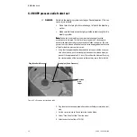
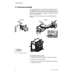
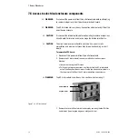
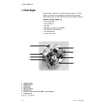
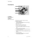
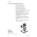
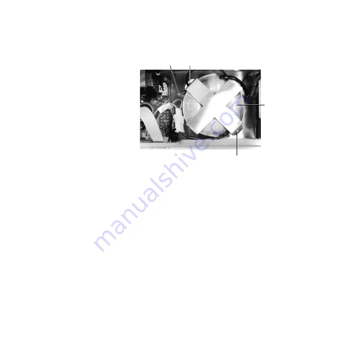
7.5.5 Toroid
(original CPU only)
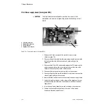
To remove the toroid, you must first remove the AC inlet module and the
electronics compartment cover. The toroid is located in the electronics
enclosure next to the power supply board.
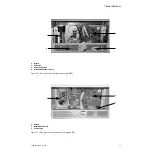
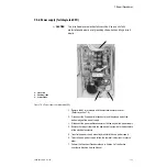
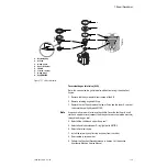
Figure 7-10 • Isolation transformer (top view)
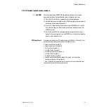
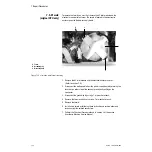
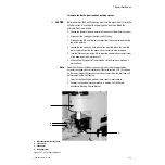
1. Remove the AC inlet module and the electrical enclosure cover
2. Disconnect the battery cable from the power supply board by pressing the
lock tabs on either side of the connector and gently pulling on the
connector.
3. Disconnect the grounding lug using a 7-mm socket wrench.
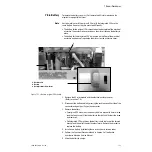
4. Remove the two mounting nuts using a 7-mm socket wrench.
5. Remove the toroid.
6. Install a new toroid by following these instructions in reverse order and
reconnecting like-colored connectors.
7. Perform the Checkout Procedure found in Section 3 of the Aestiva
Anesthesia Machine Service Manual.
3
1
2
3
3
1. Toroid
2. Grounding lug
3. Mounting nuts
Содержание Aestiva 7900 SmartVent
Страница 1: ...Aestiva 5 7900 Anesthesia Ventilator Technical Reference Manual ...
Страница 44: ...Notes 2 28 05 04 1006 0453 000 ...
Страница 81: ...4a Tests and Calibration 4 X Software 1006 0453 000 05 04 4a 35 Figure 4 38 Service Calibration full menu ...
Страница 82: ...Notes 4a 36 05 04 1006 0453 000 ...
Страница 116: ...Notes 4b 34 05 04 1006 0453 000 ...
Страница 150: ...Notes 5 34 05 04 1006 0453 000 ...
Страница 158: ...Notes 6 8 05 04 1006 0453 000 ...
Страница 182: ...Notes 7 24 05 04 1006 0453 000 ...
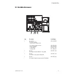
Страница 189: ...8 Illustrated Parts 1006 0453 000 05 04 8 7 U14 U23 4 12 13 14 15 16 15 18 21 20 23 24 1 1a 22 17 19 ...
Страница 202: ...Notes 8 20 05 04 1006 0453 000 ...
Страница 203: ......


