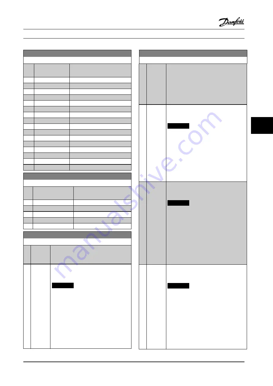
20-06 Feedback 3 Source
Option:
Function:
See
for details.
[0]
*
No function
[1]
Analog Input 53
[2]
Analog Input 54
[3]
Pulse input 29
[4]
Pulse input 33
[7]
Analog input X30/11
[8]
Analog input X30/12
[9]
Analog Input X42/1
[10]
Analog Input X42/3
[11]
Analog Input X42/5
[15]
Analog Input X48/2
[100] Bus feedback 1
[101] Bus feedback 2
[102] Bus feedback 3
[104] Sensorless Flow
[105] Sensorless Pressure
20-07 Feedback 3 Conversion
Option:
Function:
See
for details.
[0]
*
Linear
[1]
Square root
[2]
Pressure to temperature
[3]
Pressure to flow
[4]
Velocity to flow
20-20 Feedback Function
Option:
Function:
This parameter determines how the 3 possible
feedbacks are used to control the output
frequency of the adjustable frequency drive.
[0] Sum
Sets up the PID controller to use the sum of
feedback 1, feedback 2 and feedback 3 as the
feedback.
NOTICE!
Set any unused feedbacks to
[0] No
Function
in
, or
The sum of setpoint 1 and any other references
that are enabled (see
parameter group 3-1*
References
) are used as the PID controller’s
setpoint reference.
20-20 Feedback Function
Option:
Function:
[1] Difference Sets up the PID controller to use the difference
between feedback 1 and feedback 2 as the
feedback. Feedback 3 is not used with this
selection. Only setpoint 1 is used. The sum of
setpoint 1 and any other references that are
enabled (see
parameter group 3-1* References
) are
used as the PID controller’s setpoint reference.
[2] Average
Sets up the PID Controller to use the average of
feedback 1, feedback 2 and feedback 3 as the
feedback.
NOTICE!
Set any unused feedbacks to
[0] No
Function
in
,
, or
. The sum of setpoint 1 and any
other references that are enabled (see
parameter group 3-1* References
) are used
as the PID controller’s setpoint reference.
[3]
*
Minimum
Sets up the PID controller to compare feedback
1, feedback 2 and feedback 3 and uses the
lowest value as the feedback.
NOTICE!
Set any unused feedbacks to
[0] No
Function
in
,
, or
. Only setpoint 1 is used. The sum
of setpoint 1 and any other references
that are enabled (see
parameter group
3-1* References
) are used as the PID
controller’s setpoint reference.
[4] Maximum Sets up the PID controller to compare feedback
1, feedback 2 and feedback 3 and use the
highest value as the feedback.
NOTICE!
Set any unused feedbacks to
[0] No
Function
in
,
, or
.
Only setpoint 1 is used. The sum of setpoint 1
and any other references that are enabled (see
parameter group 3-1* References
) are used as the
PID controller’s setpoint reference.
How to Program
Instruction Manual
MG11F522
Danfoss A/S © 08/2014 All rights reserved.
101
6
6
Содержание VLT HVAC Drive FC 102
Страница 2: ......


