manualshive.com logo in svg
background image

MAKING MODERN LIVING POSSIBLE

Design Guide

VLT

®

 HVAC Basic Drive FC 101

www.danfoss.com/drives

Содержание VLT HVAC Basic Drive FC 101

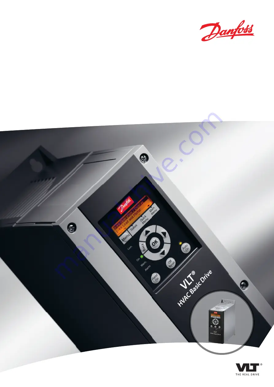
Страница 1: ...MAKING MODERN LIVING POSSIBLE Design Guide VLT HVAC Basic Drive FC 101 www danfoss com drives...

Страница 2: ......

Страница 3: ...Local Hand On and Remote Auto On Control 26 2 7 5 Control Structure Closed Loop 26 2 7 6 Feedback Conversion 26 2 7 7 Reference Handling 27 2 7 8 Closed Loop Set up Wizard 28 2 7 9 Tuning the Drive C...

Страница 4: ...s 69 6 3 4 Main Menu 78 6 4 Quick Transfer of Parameter Settings between Multiple Frequency Converters 78 6 5 Read out and Programming of Indexed Parameters 78 6 6 Initialise the Frequency Converter t...

Страница 5: ...us RTU 87 7 8 2 Modbus RTU Message Structure 87 7 8 3 Start Stop Field 88 7 8 4 Address Field 88 7 8 5 Function Field 88 7 8 6 Data Field 88 7 8 7 CRC Check Field 88 7 8 8 Coil Register Addressing 88...

Страница 6: ...ence Value 97 8 General Specifications and Troubleshooting 98 8 1 Mains Supply Specifications 98 8 1 1 Mains Supply 3x200 240 V AC 98 8 1 2 Mains Supply 3x380 480 V AC 99 8 1 3 Mains Supply 3x380 480...

Страница 7: ...d result in minor or moderate injury It may also be used to alert against unsafe practices NOTICE Indicates important information including situations that may result in damage to equipment or propert...

Страница 8: ...y converter UVLT MAX The maximum output voltage Input The connected motor can start and stop with LCP and the digital inputs Functions are divided into 2 groups Functions in group 1 have higher priori...

Страница 9: ...cy converter return to their default settings Initialising 14 22 Operation Mode does not initialise communication parameters Intermittent duty cycle An intermittent duty rating refers to a sequence of...

Страница 10: ...ing programmed to reset automatically Trip locked may not be used for personal safety VT characteristics Variable torque characteristics used for pumps and fans VVCplus If compared with standard volta...

Страница 11: ...er is connected to mains Check that the mains supply has been disconnected and that the necessary time has elapsed before removing motor and mains plugs 7 Check that all voltage inputs have been disco...

Страница 12: ...in the 50 1000 V AC and the 75 1500 V DC voltage ranges Danfoss CE labels in accordance with the directive and issues a declaration of conformity upon request The EMC directive 89 336 EEC EMC is shor...

Страница 13: ...MC properties of the appliance system or installation rests with the installer As an aid to the installer Danfoss has prepared EMC installation guidelines for the Power Drive system The standards and...

Страница 14: ...ndom Table 2 2 Standards 2 6 Advantages 2 6 1 Why use a Frequency Converter for Controlling Fans and Pumps A frequency converter takes advantage of the fact that centrifugal fans and pumps follow the...

Страница 15: ...ionality n 100 50 25 12 5 50 100 80 80 175HA208 10 Power n3 Pressure n2 Flow n Illustration 2 3 Laws of Proportionally Flow Q1 Q2 n1 n2 Pressure H1 H2 n1 n2 2 Power P1 P2 n1 n2 3 2 6 4 Comparison of E...

Страница 16: ...50 40 30 20 10 Hs 0 100 200 300 400 mwg B C A 750rpm 1050rpm 1350rpm 1650rpm 0 10 20 30 kW 40 50 60 200 100 300 m3 h m3 h 400 750rpm 1050rpm 1350rpm 1650rpm Pshaft C1 B1 A1 Illustration 2 7 Energy m3...

Страница 17: ...ed 500 100 0 0 12 5 25 37 5 50Hz 200 300 400 600 700 800 4 3 2 1 175HA227 10 Illustration 2 8 Start up Current 1 VLT HVAC Basic Drive FC 101 2 Star delta starter 3 Soft starter 4 Start directly on mai...

Страница 18: ...S Energy Management system V A V Variable Air Volume Sensor P Pressure Sensor T Temperature Table 2 6 Abbreviations used in Illustration 2 9 2 6 10 With a Frequency Converter 175HA206 11 Pump Flow Re...

Страница 19: ...e Drive to Improving Variable Air Volume Ventilation Systems MN60A Constant Air Volume Ask for The Drive to Improving Constant Air Volume Ventilation Systems MN60B Cooling Tower Fan Ask for The Drive...

Страница 20: ...saves much more energy and reduces the complexity of the installation Instead of creating an artificial pressure drop or causing a decrease in fan efficiency the frequency converter decreases the spee...

Страница 21: ...s the outside temperature varies as well as the number of people in the controlled zone changes different cooling requirements exist As the temperature decreases below the set point the supply fan can...

Страница 22: ...n also be used to turn the fan on and off as needed Several features of the Danfoss HVAC dedicated frequency converter the HVAC frequency converter can be utilised to improve the performance of coolin...

Страница 23: ...rters can be added to condenser water pumps instead of balancing the pumps with a throttling valve or trimming the pump impeller Using a frequency converter instead of a throttling valve simply saves...

Страница 24: ...eading to reduced operating expenses Two control methods are common Flow meter Because the desired flow rate is known and is constant a flow meter installed at the discharge of each chiller can be use...

Страница 25: ...ncy converter Frequency converter CHILLER CHILLER Flowmeter Flowmeter F F 130BB456 10 Illustration 2 15 Primary Pumps Product Overview VLT HVAC Basic Drive FC 101 Design Guide MG18C502 Rev 2013 09 06...

Страница 26: ...ue energy savings and control potential is realised by adding frequency converters With the proper sensor location the addition of frequency converters allows the pumps to vary their speed to follow t...

Страница 27: ...h efficient PM motors permanent magnet motors in IEC standard frame size operated by Danfoss frequency converters The commissioning procedure is comparable to the existing one for asynchronous inducti...

Страница 28: ...verter as the set point reference A static pressure sensor measures the actual static pressure in the pipe and supplies this to the frequency converter as a feedback signal If the feedback signal is g...

Страница 29: ...Illustration 2 21 Block Diagram Showing Remote Reference The remote reference is comprised of Preset references External references analog inputs and serial communication bus references The preset re...

Страница 30: ...eedback 0016 Hz 6 23 T54 high Current 13 30 A 6 25 T54 high Feedback 0050 0 01 s 20 81 PI Normal Inverse Control 0 Normal 20 83 PI Normal Inverse Control 0050Hz 20 93 PI Proportional Gain 00 50 1 29 A...

Страница 31: ...tion 1 20 Motor Power 0 09 110 kW Size related Enter motor power from nameplate data 1 22 Motor Voltage 50 0 1000 0 V Size related Enter motor voltage from nameplate data 1 23 Motor Frequency 20 0 400...

Страница 32: ...current that corresponds to the high reference value 6 23 Terminal 54 High Current 0 20 mA 20 Enter the current that corresponds to the high reference value 6 24 Terminal 54 Low Ref Feedb Value 4999...

Страница 33: ...crease it until the feedback signal begins to oscillate If necessary start and stop the frequency converter or make step changes in the set point reference to attempt to cause oscillation Next reduce...

Страница 34: ...ich reduces the screen effect and increases the leakage current I4 If a screened cable is used for relay control cable signal interface and brake mount the screen on the enclosure at both ends In some...

Страница 35: ...y converters installed in the second environment industrial with a supply voltage lower than 1000 V Class A Group 2 C4 Frequency converters installed in the second environment with a supply voltage eq...

Страница 36: ...ernal filter With external filter Without external filter With external filter Without external filter With external filter Without external filter With external filter H4 RFI filter Class A1 0 25 11...

Страница 37: ...for the frequency in question The total voltage distortion THD is calculated on the basis of the individual voltage harmonics using this formula THD U 2 5 U 2 7 U 2 N UN of U 2 8 4 Harmonics Emission...

Страница 38: ...380 480 V typical 44 4 40 8 Limit for Rsce 120 48 46 Table 2 21 Harmonic Current 0 75 18 5 kW 380 480 V Individual Harmonic Current In I1 I5 I7 I11 I13 Actual 15 45 kW IP20 200 V typical 26 7 9 7 7 7...

Страница 39: ...he EN 61800 5 1 standard The components that make up the electrical isolation as described also comply with the requirements for higher isolation and the relevant test as described in EN 61800 5 1 The...

Страница 40: ...sharing and brake outputs see the design guidelines Switching on the output Switching on the output between the motor and the frequency converter is fully permitted The frequency converter is not dama...

Страница 41: ...mechanical thermal switch Klixon type or Electronic Thermal Relay ETR 1330 550 250 20 C 175HA183 10 4000 3000 R nominel nominel 5 C nominel 5 C C Illustration 2 28 Trip due to High Motor Temperature...

Страница 42: ...log Input 10 V Power Supply Input Supply Voltage V Threshold Cut out Values Digital 10 800 2 9 k Analog 10 800 2 9 k Table 2 25 Supply Voltage NOTICE Check that the selected supply voltage follows the...

Страница 43: ...to On Alarm Warn On Com Alarm Warn On B a c k Hand OK Off Reset Auto On On Illustration 3 1 Fit Gasket Step 2 Place LCP on panel see dimensions of hole on Illustration 3 2 130BB776 11 Gasket R 1 5 _ 0...

Страница 44: ...e Kit IP21 TYPE 1 is an optional enclosure element available for IP20 units If the enclosure kit is used an IP20 unit is upgraded to comply with enclosure IP21 TYPE 1 130BB902 11 VLT HVAC Basic Drive...

Страница 45: ...220 132B0220 H10 IP20 11 15 kW 475 165 249 132B0221 132B0221 Table 3 3 Enclosure Kit Specifications 3 1 4 Decoupling Plate Use the decoupling plate for EMC correct installation Shown here on a H3 encl...

Страница 46: ...Use the Internet based Drive Configurator to configure the right frequency converter for the right application and generate the type code string The Drive Configurator automatically generates an 8 dig...

Страница 47: ...ss A1 B H2 RFI filter class A2 H3 RFI filter class A1 B reduced cable length H4 RFI filter class A1 Brake 18 X No brake chopper included Display 19 A Alpha Numeric Local Control Panel X No Local Contr...

Страница 48: ...60 55 75 75 100 90 125 T6 525 600 V AC 18 5 30 30 37 55 60 75 90 120 125 Description LCP 132B0200 LCP panel mounting kit IP55 incl 3 m cable 132B0201 Decoupling plate 132B0202 132B0202 132B0204 132B0...

Страница 49: ...176 3 8 130B1294 130B1213 Table 4 4 AHF Filters 10 current distortion 3x440 480 V 60 Hz Power kW Drive input current Continuous A Default switching frequency kHz THID level Order number filter IP00 Co...

Страница 50: ...2B0244 3 7 5 FN3258 16 45 250 45 70 220 235 25 4 5 1 10 6 M5 22 5 31 0 7 0 8 0 8 132B0245 11 15 FN3258 30 47 270 50 85 240 255 30 5 4 1 10 6 M5 25 40 1 9 2 2 1 2 132B0246 18 5 22 FN3258 42 47 310 50 8...

Страница 51: ...4 150 120 255 12 6 7 8 5 9 5 H6 IP20 15 18 5 30 45 18 5 30 518 595 635 45 kW 495 239 200 242 8 5 15 24 5 H7 IP20 22 30 55 75 37 55 550 630 690 75 kW 521 313 270 335 8 5 17 36 H8 IP20 37 45 90 75 90 66...

Страница 52: ...5 2 Enclosure Clearance mm Frame IP class Above unit Below unit H1 20 100 100 H2 20 100 100 H3 20 100 100 H4 20 100 100 H5 20 100 100 H6 20 200 200 H7 20 200 200 H8 20 225 225 H9 20 100 100 H10 20 20...

Страница 53: ...600 V AC kW Hp 18 5 30 30 40 37 55 60 70 75 90 100 125 2 2 7 5 3 0 10 11 15 15 20 IP frame IP20 IP54 Maximum weight kg 2 1 3 4 4 5 7 9 9 5 24 5 36 51 6 6 11 5 6 1 7 8 13 8 23 3 28 3 41 5 60 5 Shippin...

Страница 54: ...H3 IP20 3 7 5 5 7 5 100 4 H4 IP20 5 5 7 5 11 15 100 4 H5 IP20 11 18 5 22 100 4 H6 IP20 15 18 5 30 45 18 5 30 200 7 9 H7 IP20 22 30 55 75 37 55 200 7 9 H8 IP20 37 45 90 75 90 225 8 9 H9 IP20 2 2 7 5 10...

Страница 55: ...Interface RS 485 N PS 485 69 P RS 485 68 Com RS 485 61 PNP Source NPN Sink ON Terminated OFF Unterminated ON 1 2 240 V AC 3 A Not present on all power sizes Do not connect shield to 61 01 02 03 relay...

Страница 56: ...0 5 Table 5 5 Enclosure H1 H8 Power kW Torque Nm Frame IP class 3x380 480 V Line Motor DC connection Control terminals Earth Relay I2 IP54 0 75 4 0 1 4 0 8 0 8 0 5 0 8 0 5 I3 IP54 5 5 7 5 1 4 0 8 0 8...

Страница 57: ...ge currents For further details on mounting of the decoupling plate see FC 101 De coupling Plate Mounting Instruction Also see EMC Correct Installation in the VLT HVAC Basic Design Guide 1 Mount the e...

Страница 58: ...5 600 V 22 30 kW 1 Line 2 Motor 3 Earth 4 Relays Table 5 9 Legend to Illustration 5 3 1 2 3 4 130BB763 10 Illustration 5 4 H7 Frame IP20 380 480 V 55 75 kW IP20 200 240 V 22 30 kW IP20 525 600 V 45 55...

Страница 59: ...T302 12 Illustration 5 6 H9 Frame IP20 600 V 2 2 7 5 kW DC DC BR BR U V W 9 9 M A I N S 95 RELAY 1 RELAY 2 LC 130BA261 10 Illustration 5 7 Mount the 2 screws in the mounting plate slide it into place...

Страница 60: ...plug and tighten wires DC BR BR U V W M A I N S L1 L2 L3 91 92 93 RELAY 1 RELAY 2 99 LC 130BA264 10 Illustration 5 10 Tighten support bracket on mains wires 130BA725 10 Illustration 5 11 H10 Frame IP2...

Страница 61: ...otor 6 UDC 7 Relays 8 I O Table 5 12 Legend to Illustration 5 12 130BC201 10 Illustration 5 13 I3 Frame IP54 380 480 V 5 5 7 5 kW 1 RS 485 2 Line in 3 Earth 4 Wire clamps 5 Motor 6 UDC 7 Relays 8 I O...

Страница 62: ...C 7 Relays 8 I O Table 5 14 Legend to Illustration 5 14 130BC203 10 Illustration 5 15 IP54 I2 I3 I4 frame 130BT326 10 Illustration 5 16 I6 Frame IP54 380 480 V 22 37 kW 130BT325 10 Illustration 5 17 I...

Страница 63: ...5 18 I6 Frame IP54 380 480 V 22 37 kW 91 L1 92 L2 93 L3 96 U 97 V 98 W 88 DC 89 DC 81 R 8 R 99 95 130BA248 10 Illustration 5 19 I7 I8 Frame IP54 380 480 V 45 55 kW IP54 380 480 V 75 90 kW How to Inst...

Страница 64: ...ircuit breakers must be designed for protection in a circuit capable of supplying a maximum of 10 000 Arms symmetrical 480 V maximum NOTICE In the event of malfunction failure to follow the protection...

Страница 65: ...S R200 JKS R200 JJS R200 150 75 FRS R 200 KTS R200 JKS R200 JJS R200 200 90 Cutler Hammer JGE3250FFG Moeller NZMB2 A250 FRS R 250 KTS R250 JKS R250 JJS R250 250 3x525 600 V IP20 2 2 FRS R 20 KTS R20 J...

Страница 66: ...R 25 KTS R 25 JKS 25 JJS 25 25 11 PKZM4 63 FRS R 50 KTS R 50 JKS 50 JJS 50 63 15 PKZM4 63 FRS R 50 KTS R 50 JKS 50 JJS 50 63 18 5 PKZM4 63 FRS R 80 KTS R 80 JKS 80 JJS 80 63 22 Moeller NZMB1 A125 FRS...

Страница 67: ...tails since this ruins the screening effect at high frequencies Use the cable clamps provided instead It is important to ensure good electrical contact from the installation plate through the installa...

Страница 68: ...tput con tactor etc Motor cable Motor 3 phases and PLC etc Panel Mains supply Min 200mm between control cable mains cable and between mains motor cable PLC Protective earth Reinforced protective earth...

Страница 69: ...digital input 29 mode is set in 5 03 Digital Input 29 Mode PNP is default value 130BC249 10 Illustration 5 23 IP54 400 V 0 75 7 5 kW 1 Remove the front cover Control terminals Illustration 5 24 shows...

Страница 70: ...f the display indicated by a small arrow pointing either clockwise or counterclockwise 5 The triangle indicates if the LCP is in status quick menu or main menu Table 6 1 Legend to Illustration 6 1 B M...

Страница 71: ...uides the installer through the set up of the frequency converter to an open loop application An open loop application is here an application with a start signal analog reference voltage or current an...

Страница 72: ...K to accept Automatic Motor Adaption Off Auto Motor Adapt OK Press OK Select Function of Relay 2 No function Select Function of Relay 1 0 No function Set Max Reference Hz Set Min Reference Hz AMA runn...

Страница 73: ...nstruction 0 Asynchron 1 PM non salient SPM 0 Asynchron Setting the parameter value might change these parameters 1 01 Motor Control Principle 1 03 Torque Characteristics 1 14 Damping Gain 1 15 Low Sp...

Страница 74: ...nction is not required When is enabled 1 71 Start Delay and 1 72 Start Function have no function is active in VVCplus mode only 3 02 Minimum Reference 4999 4999 0 The minimum reference is the lowest v...

Страница 75: ...the current that corresponds to the low reference value 6 13 Terminal 53 High Current 0 20 mA 20 Enter the current that corresponds to the high reference value 6 19 Terminal 53 mode 0 Current 1 Voltag...

Страница 76: ...6 23 T54 high Current 13 30 A 6 25 T54 high Feedback 0050 0 01 s 20 81 PI Normal Inverse Control 0 Normal 20 83 PI Normal Inverse Control 0050Hz 20 93 PI Proportional Gain 00 50 1 29 Automatic Motor A...

Страница 77: ...ction 1 20 Motor Power 0 09 110 kW Size related Enter motor power from nameplate data 1 22 Motor Voltage 50 0 1000 0 V Size related Enter motor voltage from nameplate data 1 23 Motor Frequency 20 0 40...

Страница 78: ...oltage that corresponds to the low high reference value 6 22 Terminal 54 Low Current 0 20 mA 4 Enter the current that corresponds to the high reference value 6 23 Terminal 54 High Current 0 20 mA 20 E...

Страница 79: ...1 PM non salient SPM NOTICE Changing this parameter affects settings of other parameters 1 30 Stator Resistance Rs 0 000 99 990 Size related Set the stator resistance value 1 37 d axis Inductance Ld 0...

Страница 80: ...r group 4 Press to browse through the parameters in the specific group 5 Press OK to select the parameter 6 Press to set change the parameter value Press Back to go back one level 6 4 Quick Transfer o...

Страница 81: ...Over Temp s 15 05 Over Volt s 15 30 Alarm Log Error Code 15 4 Drive identification parameters 1 06 Clockwise Direction 2 finger initialisation 1 Power off the frequency converter 2 Press OK and Menu 3...

Страница 82: ...bles to maintain the same earth potential throughout the network partic ularly in installations with long cables To prevent impedance mismatch always use the same type of cable throughout the entire n...

Страница 83: ...nd brake resistor cables Normally a distance of 200 mm 8 inches is sufficient but Danfoss recommends keeping the greatest possible distance between the cables Especially where cables run in parallel o...

Страница 84: ...rity bit in total A stop bit completes a character thus consisting of 11 bits in all 0 1 3 2 4 5 6 7 195NA036 10 Start bit Even Stop Parity bit Illustration 7 3 Content of a Character 7 4 2 Telegram S...

Страница 85: ...rom follower to master ADR LGE STX PCD1 PCD2 BCC 130BA269 10 Illustration 7 5 Process Block Parameter block The parameter block is used to transfer parameters between master and follower The data bloc...

Страница 86: ...following fault report in the parameter value Error code FC Specification 0 Illegal Parameter Number 1 Parameter cannot be changed 2 Upper or lower limit exceeded 3 Subindex corrupted 4 No Array 5 Wr...

Страница 87: ...7 4 12 Conversion The various attributes of each parameter are displayed in the chapter Parameter Lists in the Programming Guide Parameter values are transferred as whole numbers only Conversion facto...

Страница 88: ...he process a controller uses to request access to another device This process includes how the Modbus RTU responds to requests from another device and how errors are detected and reported It also esta...

Страница 89: ...decimal characters The format for each byte is shown in Table 7 12 Start bit Data byte Stop parity Stop Table 7 12 Format for Each Byte Coding System 8 bit binary hexadecimal 0 9 A F 2 hexadecimal cha...

Страница 90: ...addition the follower places a unique code into the data field of the response message This tells the master what kind of error occurred or the reason for the exception Also refer to 7 8 10 Function C...

Страница 91: ...Coast stop No coast stop 05 Quick stop No quick stop 06 Freeze freq No freeze freq 07 Ramp stop Start 08 No reset Reset 09 No jog Jog 10 Ramp 1 Ramp 2 11 Data not valid Data valid 12 Relay 1 off Rela...

Страница 92: ...xx Dependent on parameter access Parameter 0 03 20 bytes space reserved pr parameter in Modbus Map Table 7 17 Adress Registers 1 Value written in Modbus RTU telegram must be one or less than register...

Страница 93: ...value A value of 1352 Decimal means that the parameter is set to 12 52 Reading 3 14 Preset Relative Reference 32bit The holding registers 3410 3411 holds the parameters value A value of 11300 Decimal...

Страница 94: ...equent bytes If the returned coil quantity is not a multiple of 8 the remaining bits in the final data byte is padded with zeros toward the high order end of the byte The Byte Count field specifies th...

Страница 95: ...addressed as 0 3 Example Read 3 03 Maximum Reference register 03030 Field Name Example HEX Follower Address 01 Function 03 read holding registers Starting Address HI 0B Register address 3029 Starting...

Страница 96: ...ress and quantity of registers preset Field Name Example HEX Follower Address 01 Function 10 Starting Address HI 04 Starting Address LO 19 No of Registers HI 00 No of registers LO 02 Error Check CRC T...

Страница 97: ...r starting conditions are met Make a selection in 8 53 Start Select to define how Bit 06 Ramp stop start gates with the corresponding function on a digital input Bit 07 Reset Bit 07 0 No reset Bit 07...

Страница 98: ...word Bit 06 No error triplock Bit 06 0 The frequency converter is not in fault mode Bit 06 1 The frequency converter is tripped and locked Bit 07 No warning warning Bit 07 0 There are no warnings Bit...

Страница 99: ...of 2 s complement The Actual Output frequency MAV is scaled in the same way as the bus reference Actual output freq STW Follower master Speed ref CTW Master follower 16bit 130BA276 11 Illustration 7 1...

Страница 100: ...0 240 V A 1 1 1 6 2 8 5 6 8 6 7 2 14 1 12 0 21 0 18 0 28 3 24 0 41 0 38 2 52 7 65 0 76 0 103 7 127 9 153 0 Intermittent 3x200 240 V A 1 2 1 8 3 1 6 2 9 5 7 9 15 5 13 2 23 1 19 8 31 1 26 4 45 1 42 0 58...

Страница 101: ...9 5 2 6 9 9 1 12 3 16 6 24 3 32 9 Continuous 3x440 480 V A 1 0 1 8 2 9 3 9 5 3 6 8 9 4 12 6 18 4 24 7 Intermittent 3x440 480 V A 1 1 2 0 3 2 4 3 5 8 7 5 10 3 13 9 20 2 27 2 Max mains fuses See 5 2 3 F...

Страница 102: ...ermittent 3x380 440 V A 38 7 45 7 62 7 77 0 92 4 113 0 154 0 182 0 Continuous 3x440 480 V A 29 3 34 6 49 2 60 6 72 5 88 6 120 9 142 7 Intermittent 3x440 480 V A 32 2 38 1 54 1 66 7 79 8 97 5 132 9 157...

Страница 103: ...2 9 38 7 Continuous 3x440 480 V A 1 8 2 9 3 9 5 3 6 8 9 4 12 6 18 4 24 7 29 3 Intermittent 3 x 440 480 V A 2 0 3 2 4 3 5 8 7 5 10 3 13 9 20 2 27 2 32 2 Max mains fuses See 5 2 3 Fuses and Circuit Brea...

Страница 104: ...0 3 165 6 Intermittent 3x380 440 V A 46 0 62 7 77 4 92 6 113 1 154 3 182 2 Continuous 3x440 480 V A 36 0 49 2 60 6 72 5 88 6 120 9 142 7 Intermittent 3 x 440 480 V A 39 6 54 1 66 7 79 8 97 5 132 9 157...

Страница 105: ...3 9 5 2 6 9 9 1 12 3 16 6 24 3 32 9 Continuous 3x440 480 V A 1 8 2 9 3 9 5 3 6 8 9 4 12 6 18 4 24 7 Intermittent 3 x 440 480 V A 2 0 3 2 4 3 5 8 7 5 10 3 13 9 20 2 27 2 Max mains fuses See 5 2 3 Fuse...

Страница 106: ...9 140 3 165 6 Intermittent 3x380 440 V A 38 7 46 0 62 7 77 4 92 6 113 1 154 3 182 2 Continuous 3x440 480 V A 29 3 36 0 49 2 60 6 72 5 88 6 120 9 142 7 Intermittent 3 x 440 480 V A 32 2 39 6 54 1 66 7...

Страница 107: ...0 9 Intermittent 3x525 550 V A 4 1 5 6 6 5 9 6 13 1 18 2 24 8 29 7 36 4 49 6 60 1 73 1 89 4 119 9 143 9 Continuous 3x551 600 V A 3 5 4 8 5 6 8 3 11 4 15 7 21 4 25 7 31 5 42 9 52 0 63 3 77 4 103 8 124...

Страница 108: ...according to EN 60664 1 overvoltage category III pollution degree 2 The unit is suitable for use on a circuit capable of delivering not more than 100 000 RMS symmetrical Amperes 240 480 V maximum Moto...

Страница 109: ...t digital output 1 k 1 Terminals 42 and 45 can also be programmed as analog output Control card RS 485 serial communicationA Terminal number 68 P TX RX 69 N TX RX Terminal number 61 Common for termina...

Страница 110: ...erature See max output current at 40 50 C in 8 1 2 Mains Supply 3x380 480 V AC Derating for high ambient temperature see 8 5 Derating according to Ambient Temperature and Switching Frequency8 5 Derati...

Страница 111: ...14 0 Inverter Switching Resonance Dampening 1 64 Resonance Dampening The acoustic noise from the frequency converter comes from 3 sources 1 DC intermediate circuit coils 2 Integral fan 3 RFI filter c...

Страница 112: ...0 502 2244 25 240 0 22 0 598 2175 50 240 0 292 0 615 1678 200 V 11 kW 36 240 0 176 0 56 2545 50 240 0 216 0 599 2204 400 V 0 37 kW 5 400 0 160 0 808 4 050 25 400 0 240 1 026 3 420 50 400 0 340 1 056...

Страница 113: ...0 592 1 29 1 743 100 500 0 656 1 28 1 561 150 500 0 84 1 26 1 2 400 V 37 kW 10 400 0 276 0 928 2 69 50 400 0 432 1 02 1 889 10 480 0 272 1 17 3 441 50 480 0 384 1 21 2 521 10 500 0 288 1 2 3 333 50 50...

Страница 114: ...5 10 16 40o C 50o C 45o C fsw kHz 130BC217 10 Illustration 8 1 200 V IP20 H1 0 25 0 75 kW fsw kHz 2 0 10 0 10 20 30 40 50 60 70 80 90 100 110 Iout 16 40 45 50 5 o C o C o C 130BC218 10 Illustration 8...

Страница 115: ...o C o C 130BC224 10 Illustration 8 8 400 V IP20 H4 11 15 kW fsw kHz 2 0 10 0 10 20 30 40 50 60 70 80 90 100 110 Iout 16 40 45 50 5 o C o C o C 130BC225 10 Illustration 8 9 200 V IP20 H5 11 kW fsw kHz...

Страница 116: ...C230 10 Illustration 8 14 600 V IP20 H6 22 30 kW Iout fsw kHz 20 2 4 6 8 10 12 40 60 80 40o C 45o C 50o C 100 110 130BC231 10 Illustration 8 15 200 V IP20 H7 22 30 kW Iout fsw kHz 20 2 4 6 8 10 12 40...

Страница 117: ...36 10 Illustration 8 20 600 V IP20 H8 75 90 kW Iout fsw kHz 20 2 4 6 8 10 12 40 60 80 40o C 45o C 50o C 100 110 130BC237 10 Illustration 8 21 600 V IP20 H9 2 2 3 kW Iout fsw kHz 20 2 4 6 8 10 12 40 60...

Страница 118: ...20 10 0 o 40 C 12 14 16 fsw kHz Illustration 8 26 400 V IP54 I4 11 18 5 kW 2 20 4 6 8 10 12 14 16 40 60 80 100 110 fsw kHz 45 C 50 C 55 C 0 0 Iout NO 130BA403 11 B1 B2 Illustration 8 27 400 V IP54 I5...

Страница 119: ...BC242 10 Illustration 8 30 400 V IP54 I7 45 55 kW Iout fsw kHz 20 2 4 6 8 10 12 40 60 80 40o C 45o C 50o C 100 110 130BC243 10 Illustration 8 31 400 V IP54 I8 75 90 kW General Specifications and VLT H...

Страница 120: ...pen Loop 25 Terminals 67 Word 94 Controlling Fans and Pumps 12 Cooling Tower Fan 20 D Dampers 18 DANGEROUS VOLTAGE 9 Data Types Supported by the Frequency Converter 85 DC brake 95 Decoupling Plate 43...

Страница 121: ...anual PI Adjustment 31 Menu Key 68 Menus 69 Modbus Communication 81 Exception Codes 91 RTU 87 RTU Overview 86 Moment of inertia 38 Motor output U V W 106 phases 38 protection 106 set up 69 thermal pro...

Страница 122: ...ns 69 Status Status 69 Word 96 Surroundings 108 Switching on the input supply 106 on the output 38 T Telegram Length LGE 82 The EMC directive 89 336 EEC 10 low voltage directive 73 23 EEC 10 machinery...

Страница 123: ...Index VLT HVAC Basic Drive FC 101 Design Guide MG18C502 Rev 2013 09 06 121...

Страница 124: ...www danfoss com drives MG18C502 130R0222 MG18C502 Rev 2013 09 05...

Отзывы: