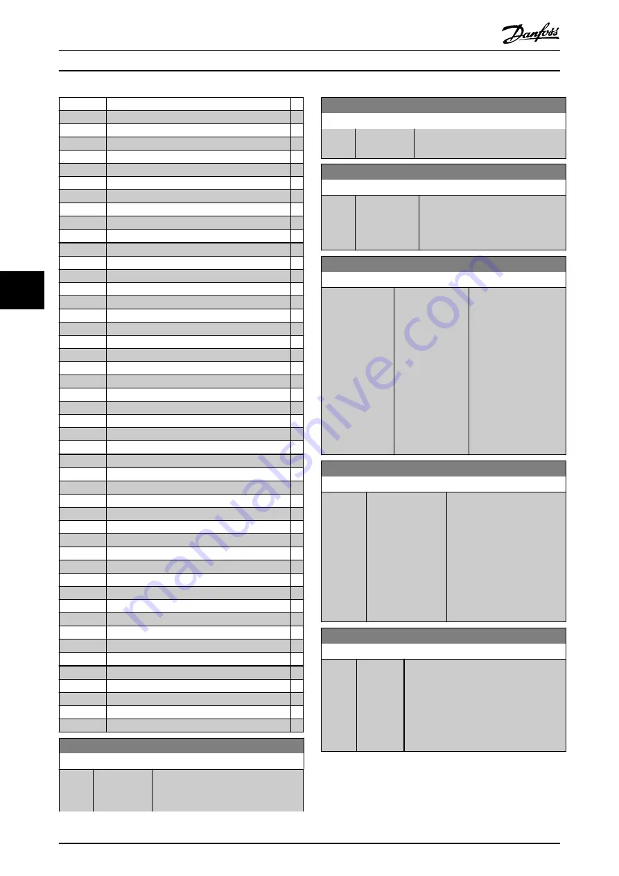
[22]
Ready, no thermal w
[25]
Reverse
[26]
Bus OK
[27]
Torque Limit & Stop
[28]
Brake, No Warning
[29]
Brake Ready, No Fault
[30]
Brake Fault (IGBT)
[31]
Relay 123
[32]
Mech brake ctrl
[33]
Safe stop active
[35]
External Interlock
[36]
Control Word Bit 11
[37]
Control Word Bit 12
[40]
Out of Ref. Range
[41]
Below Reference, low
[42]
Above Ref. high
[45]
Bus ctrl
[46]
Bus ctrl, 1 if timeout
[47]
Bus ctrl, 0 if timeout
[60]
Comparator 0
[61]
Comparator 1
[62]
Comparator 2
[63]
Comparator 3
[64]
Comparator 4
[65]
Comparator 5
[70]
Logic Rule 0
[71]
Logic Rule 1
[72]
Logic Rule 2
[73]
Logic Rule 3
[74]
Logic Rule 4
[75]
Logic Rule 5
[80]
SL Digital Output A
[81]
SL Digital Output B
[82]
SL Digital Output C
[83]
SL Digital Output D
[84]
SL Digital Output E
[85]
SL Digital Output F
[120]
Local Ref. Active
[121]
Remote Ref. Active
[122]
No Alarm
[123]
Start Cmd. Active
[124]
Running Reverse
[125]
Drive in Hand Mode
[126]
Drive in Auto Mode
[195]
Bypass Valve Control
[211]
Cascade Compressor 1
[212]
Cascade Compressor 2
[213]
Cascade Compressor 3
5-50 Term. 29 Low Frequency
Range:
Function:
100 Hz
*
[0 - 110000
Hz]
Enter the low frequency limit
corresponding to the low motor shaft
speed (i.e. low reference value) in
5-50 Term. 29 Low Frequency
Range:
Function:
5-52 Term. 29 Low Ref./Feedb. Value
.
Refer to the diagram in this section.
5-51 Term. 29 High Frequency
Range:
Function:
100 Hz
*
[0 - 110000
Hz]
Enter the high frequency limit
corresponding to the high motor shaft
speed (i.e. high reference value) in
5-53 Term. 29 High Ref./Feedb. Value
.
5-52 Term. 29 Low Ref./Feedb. Value
Range:
Function:
0 ReferenceFeed-
backUnit
*
[-999999.999 -
999999.999
ReferenceFeed-
backUnit]
Enter the low reference
value limit for the motor
shaft speed [RPM]. This
is also the lowest
feedback value, see also
5-57 Term. 33 Low Ref./
Feedb. Value
. Set
terminal 29 to digital
input (
5-02 Terminal 29
Mode
=
[0] input
(default) and
5-13 Terminal 29 Digital
Input
= applicable value).
5-53 Term. 29 High Ref./Feedb. Value
Range:
Function:
Size
related
*
[-999999.999 -
999999.999
ReferenceFeed-
backUnit]
Enter the high reference value
[RPM] for the motor shaft
speed and the high feedback
value, see also
. Select
terminal 29 as a digital input
(
5-02 Terminal 29 Mode
=
[0]
input
(default) and
5-13 Terminal 29 Digital Input
=
applicable value).
5-54 Pulse Filter Time Constant #29
Range:
Function:
100 ms
*
[1 - 1000
ms]
Enter the pulse filter time constant. The
pulse filter dampens oscillations of the
feedback signal, which is an advantage if
there is a lot of noise in the system. A
high time constant value results in better
dampening but also increases the time
delay through the filter.
NOTE
This parameter cannot be adjusted while the motor is
running.
Parameter Descriptions
Operating Instructions VLT
®
CDS302 and CDS303
66
MG34M302 - VLT
®
is a registered Danfoss trademark/Commercial Compressor
6
6


