


AKD 5000
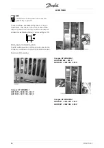
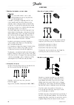
Installation
Tightening-up torque: 0.5-0.6 Nm
Screw size: M3
See section
earthing of braided screened/armoured
control cables.
No.
Function
1
1
1
12
2
2
2,,,, 1
1
1
13
3
3
3
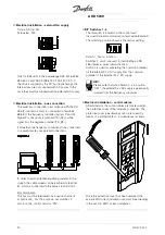
Voltage supply to digital inputs
For the 24 V DC to be usable
for the digital inputs, switch 4 on
the control card must be closed.
position "ON".
1
1
1
16
6
6
6----3
3
3
33
3
3
3
Digital inputs/encoder inputs
2
2
2
20
0
0
0
Ground for digital inputs
3
3
3
39
9
9
9
Ground for analogue/digital
outputs
4
4
4
42
2
2
2,,,, 4
4
4
45
5
5
5
Analogue/digital outputs for
indicating frequency, reference,
current and torque
5
5
5
50
0
0
0
Supply voltage to potentiometer
and thermistor 10 V DC
5
5
5
53
3
3
3,,,, 5
5
5
54
4
4
4
Analogue reference input, voltage
0 - ±10 V
5
5
5
55
5
5
5
Ground for analogue reference
inputs
6
6
6
60
0
0
0
Analogue reference input, current
0/4-20 mA
6
6
6
61
1
1
1
Termination for serial
communication. See section
Bus connection.
This terminal is
normally not to be used.
6
6
6
68
8
8
8,,,, 6
6
6
69
9
9
9
RS 485 interface, serial
communication. Where the
frequency converter is connected
to a bus, switches 2 and 3
(switches 1- 4) must be closed
on the first and the last frequency
converter. On the remaining
frequency converters, switches 2
and 3 must be open. The factory
setting is closed (position "ON").
MG.50.R3.02 -
41
Содержание AKD 5001
Страница 12: ...AKD 5000 Introduction Ordering form AKD 5000 Series Typecode MG 50 R3 02 11 ...
Страница 25: ...AKD 5000 Type F IP54 MG 50 R3 02 24 ...
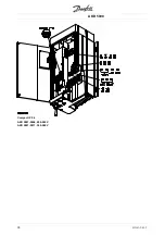
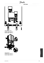
Страница 29: ...AKD 5000 Compact IP 54 AKD 5001 5006 200 240 V AKD 5001 5011 380 500 V MG 50 R3 02 28 ...
Страница 33: ...AKD 5000 MG 50 R3 02 32 ...


