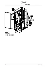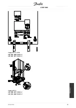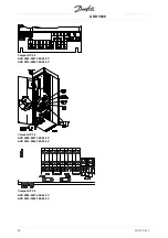
AKD 5000
Installation
In systems with motors connected in parallel, the
electronic thermal relay (ETR) of the frequency
converter cannot be used as motor protection
for the individual motor. Consequently, additional
motor protection is required, such as thermistors
in each motor (or individual thermal relays) suitable
for frequency converter use.
Please note that the individual motor cable for each
motor must be summed and is not to exceed the
total motor cable length permitted.
■
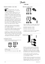
Electrical installation - brake cable
(Only standard with brake and extended with
brake. Typecode: SB, EB).
No.
Function
8
8
8
81
1
1
1,,,, 8
8
8
82
2
2
2
Brake resistor terminals
The connection cable to the brake resistor must be
screened. Connect the screen by means of cable
clamps to the conductive back plate at the frequency
converter and to the metal cabinet of the brake resistor.
Size the brake cable cross-section to match
the brake torque. See also Brake instructions,
MI.90.FX.YY and MI.50.SX.YY for further information
regarding safe installation.
NB!:
Please note that voltages up to 960 V DC,
depending on the supply voltage, may
occur on the terminals.
■
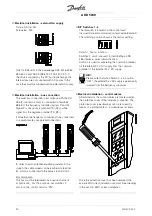
Electrical installation - relay outputs
Torque: 0.5 - 0.6 Nm
Screw size: M3
No.
Function
1
1
1
1----3
3
3
3
Relay output, 1+3 break, 1+2 make
See parameter 323 of the Operating
Instructions. See also
General
technical data.
4
4
4
4,,,, 5
5
5
5
Relay output, 4+5 make See
parameter 326 of the Operating
Instructions.
See also
General technical data.
MG.50.R3.02 -
39
Содержание AKD 5001
Страница 12: ...AKD 5000 Introduction Ordering form AKD 5000 Series Typecode MG 50 R3 02 11 ...
Страница 25: ...AKD 5000 Type F IP54 MG 50 R3 02 24 ...
Страница 29: ...AKD 5000 Compact IP 54 AKD 5001 5006 200 240 V AKD 5001 5011 380 500 V MG 50 R3 02 28 ...
Страница 33: ...AKD 5000 MG 50 R3 02 32 ...


