AK-CH
650
Capacity
controller RS8ER302 © Danfoss 2016-02
93
Capacity control of the condenser can be accomplished via step
regulation or speed control of the fans.
• Step regulation
The controller can control up to 8 condenser steps that are cut in
and out sequentially.
• Speed control
The analog output voltage is connected to a speed control. All
fans will now be controlled from 0 to max. capacity. If an ON/
OFF signal is required it can be obtained from a relay output.
Regulation can be carried out based on one of the following
principles:
- all fans operate at the same speed
- Only the necessary number of fans is cut in.
- Combination with one fan speed regulated and the rest step
regulated
Capacity control of condenser
The cut-in condenser capacity is controlled by the condenser pres-
sure’s actual value and depends on whether the pressure is rising
or falling. Regulation is performed by a PI controller which may
however be changed into a P controller if the design of the plant
necessitates this.
PI regulation
The controller cuts in capacity in such a way that the deviation
between the actual condensing pressure and the reference value
becomes as small as possible.
P regulation
The controller cuts in capacity that depends on the deviation
between the actual condensing pressure and the reference value.
The proportional band Xp indicates the deviation at 100%
condenser capacity.
Capacity curve
On air-cooled condensers, the first capacity step will always give
comparatively more capacity than the subsequent capacity steps.
The increase in capacity produced by each extra step decreases
gradually as more and more steps are cut in.
This means that the capacity controller requires more amplifica-
tion at high capacities than at low capacities. Consequently, the
capacity controller for condenser regulation functions with an
arc-shaped capacity curve so that amplification is optimal at both
high and low capacities.
On some units, compensation is already made for the "problem"
described above, by binary connection of the condenser fans: i.e.
a few fans are connected at low capacity and many fans at high
capacity, for example 1-2-4-8 etc. In this case, the non-linear am-
plification is already compensated for, and there is no need for an
arc-shaped capacity curve.
It is therefore possible to choose on the controller whether you
require an arc-shaped or a linear capacity curve to manage the
condenser capacity.
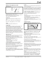
Capacity curve = Linear / Power
Capacity curve = Power Capacity curve = Linear
Regulating sensor selection
The capacity distributor can either regulate from the condenser
pressure PC or from the average temperature S7.
Cap. Ctrl sensor = Pc /S7
If the regulation sensor is selected for media temperature S7, then
Pc is still used as the safety function for high condenser pressure
and will therefore ensure cut-out of the compressor capacity when
condenser pressure is too high.
Handling sensor errors:
Cap. Ctrl. Sensor = Pc
If Pc is used as the regulation sensor, an error in the signal will
result in a cut-in of 100% condenser capacity, but the compressor
regulation will remain normal.
Cap Ctrl. Sensor = S7
If S7 is used as the regulation sensor, an error in this sensor will
result in further regulation that follows the Pc signal, but in accord-
ance with a reference that is 5K over the actual reference. If there is
an error on both S7 and Pc, 100% condenser capacity cuts-in, but
the compressor regulation remains normal.
Condenser


