46
Capacity
controller RS8ER302 © Danfoss 2016-02
AK-CH
650
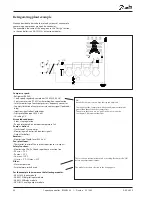
Refrigerating plant example
We have decided to describe the setup by means of an example
comprising a compressor group and a condenser.
The example is the same as the one given in the "Design" section,
i.e. the controller is an AK-CH 650 + extension modules.
Compressor pack:
• Refrigerant R404A
• 1 only speed-regulated compressor (30 kW, 30-60 Hz)
• 3 only compressors (15 kW) with working-hour equalisation
• Safety monitoring of each comp frequency converter
• Capacity limitation of compressors via contact signal (load shed-
ding)
• Injection signal to heat exchanger
• Frost protection input (230 V a.c.)
• S4 setting 2°C
Air cooled condenser:
• 4 fans, step regulation
• Pc regulates based on outdoor temperature Sc3
Pumps + defrost:
• Start/stop of 2 twin pumps
• Monitoring via flow switch (contact signal)
• Output for defrost
Receiver:
• Monitoring of liquid level (230 V a.c.)
Fan i plant room:
• Thermostat control of fan in plant room ( output)
Safety functions:
• Monitoring of Po, Pc, Sd and superheat on suction line
• P0 min. = -10°C
• Pc max. = 50°C
• Sd max. = 120°C
• SH min. = 5°C, SH max = 35°C
Other:
• Alarm output used
• External main switch used
For the example shown we use the following modules:
• AK-CH 650 basic module
• AK-XM 102B digital input module
• AK-XM 204B relay module
• AK-OB 110 analog output module
There is also an internal main switch as a setting. Both must be “ON”
before any adjustment is made.
The modules used are selected in the design phase.
NB!
Not all the compressors can have their speed adjusted.
The capacity of the compressor with speed adjustment should be
greater than that of the other compressors.
This ensures that there are no "gaps" in the cut in capacity.
See chapter 5, Adjustment functions.


