30
Capacity
controller RS8ER302 © Danfoss 2016-02
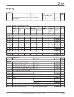
AK-CH
650
1
2
AK-CH 650
Application
Regulation of a compressor group
x
Regulation of a condenser group
x
Both compressor group and condenser group
x
Pumpe control
x
Regulation of compressor capacity
PI-regulation
x
Max. number of compressors
6
Max. number of unloaders each compressor
3
Identical compressor capacities
x
Different compressor capacities
x
Sequentiel operation (first in / last out)
x
Speed regulation of 1 or 2 compressors
x
Run time equalisation
x
Min. restart time
x
Min. On-time
x
Liquid injection in heat exchanger
x
Liquid injection in suction line
x
Load shedding (Capacity limitation)
x
Relay output, which is activated by a request for extra cooling
x
0-10 V signal, which shows cutin compressor capacity
x
Brine temperature reference
Override via P0 optimisation
x
Override via “night setback”
x
Override via "0 -10 V signal"
x
Regulation of condenser capacity
Step regulation
x
Design of a compressor and condenser control
Procedure:
1. Make a sketch of the system in question
2. Check that the controller’s functions cover the required applica-
tion
3. Consider the connections to be made
4. Use the planning table. / Note down the number of connections
./ add up
5. Are there enough connections on the controller module? – If
not, can they be obtained by changing an ON/OFF input signal
from voltage signal to contact signal, or will an extension mod-
ule be required?
6. Decide which extension modules are to be used
7. Check that the limitations are observed
8. Calculate the total length of modules
8. The modules are linked together
10. The connection sites are established
11. Draw a connection diagram or a key diagram
12. Size of supply voltage/transformer
Sketch
Make a sketch of the actual plant.
Follow these 12
steps
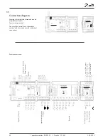
Compressor and condenser functions


