background image

52 

Capacity 

controller RS8ER302 © Danfoss 2016-02 

AK-CH 

650

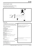
1. Go to Configuration menu

2. Select Suction group

3. Set values for the reference


Press the +-button to go on to the 

next page 

4. Set values for capacity control

Configuration - continued

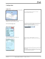
The configuration menu in the 

Service Tool has changed now. 

It  

shows the possible settings for the 

selected plant type.


In our example we select:

- 4 compressors

- P0 as signal to the regulation  

- Refrigerant = R404A 

- Equalisation of working hours

- Value for speed regulation 

   Speed regulation can always only 

be on compressor number 1. 

The settings are shown here in the 

display.

Not all compressors can have their 

speed adjusted. If there is any doubt, 

contact your compressor supplier.

In our example we select the 

settings: 

- Suction set point = -15°C 

- Night offset value = 5 K. 

The settings are shown here in the 

display.

There are several pages, one after 

the other. 

The black bar in this field tells you 

which of the pages is currently 

displayed.

Move between the pages using the 

+ and - buttons.

3 - Reference mode

Displacement of suction pressure as a function of external 

signals

0: Reference = set ref night offset from 

external 0-10 V signal

1: Reference = set ref offset from P0 optimization 

+ Night displacement

Set point ( -80 to +30°C)

Setting of required suction pressure in °C

Offset via Ext. Ref

Select whether a 0-10V external reference override signal 

is required

Offset at max input (-100 to +100 °C)

Displacement of reference at max. Ext. Ref. signal

Offset at min input (-100 to +100 °C)

Displacement of reference at min. Ext. Ref signal

Offset filter (10 - 1800 Sec)

Filter for displacement of reference, higher value results in 

slower displacement

Night select via DI

Select whether a digital input is required for activation 

of night operation. Night operation can alternatively be 

controlled via internal weekly schedule or from the system 

manager via data communication

Night Offset (-25 to +25 K)

Displacement of the brine temperature during night 

operation (set in Kelvin)

Offset via S3

The reference selection must be displaced by a signal from 

S3.

Tref S3 offset

Set the S3 temperature where it is not to be offset.

K1 S3 offset

Set the size of the change to be made in the reference 

when the S3 temperature deviates 1 degree from the set-

ting. (-10 to 10 K)

Max reference (-50 to +80 °C) 

Max. permissible brine reference

Min reference (-80 to +25 °C)

Min. permissible brine reference.

4 - Compressor application

Select the compressor application required

No. of compressors 

Set number of compressors

No. of unloaders

Set number of unloader valves

Regulation sensor

Select either P0 or S4

P0 Refrigerant

Select refrigerant type

Po refrigerant factors K1, K2, K3

Only used if “Po refrigerant type” is set to custom (contact 

Danfoss for information)

Step control mode

Select coupling pattern for compressors

Sequential: Compressors are cut in/out in strict accordance 

with compressor number (FILO)

Cyclic: Runtime equalisation between compressors (FIFO)

Best fit:  Compressors are cut in/out in order to make the 

best possible fit to actual load

Injection heat exchanger

If the function is selected, injection can be coordinated 

with compressor operation in one of two ways:

Synchronisation: Simultaneously with compressor opera-

tion.

Pump down: Like synchronisation, but it is terminated with 

pump down, where the valve is shut and the last compres-

sor disengaged once "Pump down limit" is reached.

Pump down

Select whether a pump down function is required on the 

last running compressor

Set control of compressors

If you want to know more about the different configuration 

options, they are listed below.

The number refers to the number and picture in the column 

on the left.

Содержание AK-CH 650

Страница 1: ...Capacity controller for water chillers AK CH 650 SW 2 0 User Guide ADAP KOOL Refrigeration control systems...

Страница 2: ...ion 48 System setup 50 Set plant type 51 Set control of compressors 52 Setup control of condenser 55 Setup Display 57 Setup defrost 58 Setup general alarm inputs 59 Setup separate thermostat functions...

Страница 3: ...omp Relay output which is activated by a request for extra cooling Speed control of one or two compressors Up to 6 safety inputs for each compressor Capacity limitation to minimize consumption peaks T...

Страница 4: ...have to be mounted If the system grows and more functions have to be controlled the regulation can be extended With extra modules more signals can be received and more relays cut in and out how many...

Страница 5: ...nking The controller can be linked up into a network together with other controllers in an ADAP KOOL refrigeration control system After the setup operation can be performed at a distance with say our...

Страница 6: ...an information display on the screen A corresponding display exists for all earlier alarms Here you can upload information if you need further details about the alarm history Trouble shooting The con...

Страница 7: ...t with a specific software and by which input and output signals the relevant application will require If it is an application with few connections the controller module top part with belonging bottom...

Страница 8: ...anned set up it will generate a need for a number of connections distributed on the mentioned types This connection must then be made on either the controller module or an extension module The only th...

Страница 9: ...cable and AK controller Cable between PDA cable and AK controller AK RS 232 Cable set converter between PC and AK controller AK USB Accessories Power supply module 230 V 115 V to 24 V AK PS 075 18 VA...

Страница 10: ...to the same output group Solid state outputs Can be used for loads that are cut in and out frequently e g rail heat fans and AKV valve Max 240 V a c Min 48 V a c Max 0 5 A Leak 1 mA Max 1 AKV Ambient...

Страница 11: ...2 Danfoss 2016 02 11 Dimensions The module dimension is 72 mm Modules in the 100 series consist of one module Modules in the 200 series consist of two modules Controllers consist of three modules The...

Страница 12: ...unication Address setting When the controller is connected to a gateway type AKA 245 the controller s address must be set between 1 and 119 Service PIN When the controller is connected to the data com...

Страница 13: ...I 2 3 4 3 AI 3 5 6 4 AI 4 7 8 5 AI 5 9 10 6 AI 6 11 12 7 AI 7 13 14 8 AI 8 19 20 9 AI 9 21 22 10 AI 10 23 24 11 AI 11 25 26 12 DO 1 31 32 13 DO 2 33 34 14 DO 3 35 36 15 DO 4 37 38 16 DO 5 39 40 41 17...

Страница 14: ...signals Supply voltage The supply voltage to the module comes from the previous module in the row Supply voltage to a pressure transmitter can be taken from either the 5 V output or the 12 V output de...

Страница 15: ...R AKS 32 P0A P0B PcA PcB AKS 32R AKS 2050 MBS 8250 1 xx bar AKS 32 1 zz bar U 0 5 V 0 10 V On Off Ext Main switch Day Night Door Active at Closed Open Point 5 6 7 8 Type AI5 AI6 AI7 AI8 Point 1 2 3 4...

Страница 16: ...Function The module contains 8 inputs for on off voltage signals Signal AK XM 102A is for low voltage signals AK XM 102B is for high voltage signals Supply voltage The supply voltage to the module com...

Страница 17: ...DI 2 3 4 3 DI 3 5 6 4 DI 4 7 8 5 DI 5 9 10 6 DI 6 11 12 7 DI 7 13 14 8 DI 8 15 16 Point Signal Active at DI Ext Main switch Day Night Comp safety 1 Comp safety 2 Closed voltage on Open voltage off Po...

Страница 18: ...m the previous module in the row Supply voltage to a pressure transmitter can be taken from either the 5 V output or the 12 V output depending on transmitter type Galvanic isolation The inputs are gal...

Страница 19: ...PcA PcB Paux Pgc Prec AKS 32R AKS 2050 MBS 8250 1 xx bar AKS 32 1 zz bar U 0 5 V 0 10 V On Off Ext Main switch Day Night Door Level switch Active at Closed Open AO 0 10 V Terminal 9 12 V Terminal 10 5...

Страница 20: ...he relay s function Either to position OFF or ON In position Auto the controller carries out the control Light emitting diodes There are two rows with LED s They indicate the following Left row Voltag...

Страница 21: ...Module Point Terminal Active at 1 DO 1 25 26 27 2 DO 2 28 27 30 3 DO 3 31 32 33 4 DO 4 34 35 36 5 DO 5 37 38 39 6 DO 6 40 41 42 7 DO 7 43 44 45 8 DO 8 46 47 48 Signal Active at DO Comp 1 Comp 2 Fan 1...

Страница 22: ...over switches at the front make it possible to override the relay s function Either to position OFF or ON In position Auto the controller carries out the control Light emitting diodes There are two ro...

Страница 23: ...type S Pt 1000 ohm 0 C S1 S2 Saux1 Saux2 SSA SdA Pt 1000 P AKS 32R AKS 32 P0A P0B PcA PcB AKS 32R AKS 2050 MBS 8250 1 xx bar AKS 32 1 zz bar U 0 5 V 0 10 V On Off Ext Main switch Day Night Door Activ...

Страница 24: ...Supply voltage The supply voltage to the module comes from the controller module Placing The module is placed on the PC board in the controller module Point The two outputs have points 24 and 25 They...

Страница 25: ...es for day night change over Fixed defrost times Saving of alarm log in case of power failure Saving of temperature log in case of power failure Connection The module is provided with plug connection...

Страница 26: ...that can occur Connection The extension module is connected to the controller module via a cable with plug connections You have to use one cable per module The cable is supplied in various lengths Bo...

Страница 27: ...pply voltage 230 V a c or 115 V a c from 100 V a c to 240 V a c Placing On DIN rail Effect Type Output tension Output current Power AK PS 075 24 V d c 0 75 A 18 VA AK PS 150 24 V d c adjustable 1 5 A...

Страница 28: ...lock function and change over between summer time and winter time are contained in the controller The clock is zeroset when there is power failure The clock s setting is maintained if the controller i...

Страница 29: ...t be set ON OFF voltage inputs DI This signal must be connected to two terminals The signal must have two levels either 0 V or voltage on the input There are two different extension modules for this s...

Страница 30: ...erride via P0 optimisation x Override via night setback x Override via 0 10 V signal x Regulation of condenser capacity Step regulation x Design of a compressor and condenser control Procedure 1 Make...

Страница 31: ...5 Max number of steps 8 Speed regulation x Step and speed regulation x Speed regulation on first step x Limitation of speed during night operation x Heat recovery function via thermostat function x H...

Страница 32: ...ompressor Request extra cooling capacity Fan motor 1 8 Start stop of liquid injection in heat exchanger Defrost output Start stop of liquid injection in suction line Start stop of heat recovery Start...

Страница 33: ...circuits condenser fans Safety circuits frequency converter comp cond 1 Defrost start External start stop 1 Night setback of suction pressure Flow switch Separate alarm functions 1 1 Heat recovery vi...

Страница 34: ...he controller will all the time check whether there is connection to the connected modules This status can be followed by the light emitting diode When the two catches for the DIN rail mounting are in...

Страница 35: ...D compressor speed 5 DI 5 9 10 Open Frost protection 6 DI 6 11 12 Open DI alarm Receiver level 7 DI 7 13 14 Open 8 DI 8 15 16 Hint In appendix B 16 general installation types are illustrated If your i...

Страница 36: ...protection Receiver level alarm Liquid injection in heat exchanger Pump flow switch 1 2 3 Connection diagram Drawings of the individual modules may be ordered from Danfoss Format dwg and dxf You may t...

Страница 37: ...sumption grows with the number of modules used Module Type Number Effect Controller 1 x 8 8 VA Extension module 200 series _ x 5 __ VA Extension module 100 series _ x 2 __ VA Total ___ VA Example cont...

Страница 38: ...odem cable and AK controller Cable between PDA cable and AK controller AK RS 232 080Z0261 Cable set converter between PC and AK controller AK USB 080Z0264 Accessories Power supply module 230 V 115 V t...

Страница 39: ...is section describes how the controller Is fitted Is connected We have decided to work on the basis of the example we went through previously i e the following modules AK CH 650 controller module AK X...

Страница 40: ...the plate on the left hand side of the light emitting diodes and the plate on the right hand side for the red address changers Lift the top part off the basic module 2 Mount the extension module in t...

Страница 41: ...dule and the basic module The basic module must not be connected to voltage In our example two extension modules are to be fitted to the basic module We have chosen to fit the module with relays direc...

Страница 42: ...rature Sd 8 AI 8 19 20 Pt 1000 Suction gas temperature Ss 9 AI 9 21 22 Pt 1000 Suction pressure P0 10 AI 10 23 24 AKS32 12 Condenser pressure Pc 11 AI 11 25 26 AKS32 34 Compressor 1 VSD 12 DO 1 31 32...

Страница 43: ...ply voltage Is 24 V and the supply must not be used by other controllers or devices The terminals must not be earthed 4 Follow light emitting diodes When the supply voltage is connected the controller...

Страница 44: ...44 Capacity controller RS8ER302 Danfoss 2016 02 AK CH 650...

Страница 45: ...ion and operation This section describes how the controller Is configured Is operated We have decided to work on the basis of the example we went through previously i e compressor control with 4 compr...

Страница 46: ...frost Start stop of 2 twin pumps Monitoring via flow switch contact signal Output for defrost Receiver Monitoring of liquid level 230 V a c Fan i plant room Thermostat control of fan in plant room sen...

Страница 47: ...an overview of it will always appear In this case the overview is empty This is because the controller has not yet been set up The red alarm bell at the bottom right tells you that there is an active...

Страница 48: ...menu An updated version of the service tool will be released in the spring of 2009 If the controller is operated with the new version language selec tion will happen automatically in connection with t...

Страница 49: ...lock Press the blue field with the text Locked 4 Select Unlocked Configuration continued The controller can only be configured when it is unlocked It can only be adjusted when it is locked Changes to...

Страница 50: ...in the blue field with the setting and then indicating the value of the required setting In the first field you enter a name for what the controller will be control ling When the time is set the PC s...

Страница 51: ...s how much of the compressor capacity is cutin We do not use this signal in the example When the installation type is to be configured it can be done in two ways Either one of these two we chose to us...

Страница 52: ...ed for activation of night operation Night operation can alternatively be controlled via internal weekly schedule or from the system manager via data communication Night Offset 25 to 25 K Displacement...

Страница 53: ...rride delay 1 Max time for capacity limit if P0 is too high Override delay 2 Max time for capacity limit if P0 is too high Advanced control settings Select whether the advanced capacity control settin...

Страница 54: ...n line SH alarm delay Time delay before alarm for min max superheat in suction line 8 Compressor safety Frost protection Choose whether an overall joint security inlet for all com pressors is desired...

Страница 55: ...very No Heat recovery not used Thermostat Heat recovery operated from thermostat Digital input Heat recovery operated from signal on a digital input Heat recovery relay Choose whether an output is req...

Страница 56: ...an be used to limit fan speed at night in order to limit the noise level Monitor Air flow Choose whether monitoring is required of the condenser s air flow via an intelligent error detection method Mo...

Страница 57: ...Cond control sensor Pc Pc Bar abs S7 Unit readout Choose whether readings are to be in SI units C and bar or US units F and psi Setup Display 1 Go to Configuration menu 2 Select Display setup 3 Defin...

Страница 58: ...defrost time Max permitted defrost time Refrigeration will always start once this time has passed Drip delay Time after defrost end where the water is drip ping from the refrigeration surfaces Defros...

Страница 59: ...one alarm function for monitoring the liquid level in the receiver We have subsequently selected a name for the alarm function and for the alarm text 3 General alarm input This function can be used t...

Страница 60: ...stat has a separate outlet to control external automa tion No of thermostats Set the number of general thermostats For each thermostat adjust Name Which of the sensors is used Actual temp Temperature...

Страница 61: ...to define this relay if all you require is an alarm message via the data communication Setup separate voltage functions 3 Voltage inputs The general volt inlet can be used to monitor external voltage...

Страница 62: ...DO5 2 5 ON Fan in plant room DO6 2 6 ON Alarm DO7 2 7 OFF DO8 2 8 The alarm is inverted so that there will be an alarm if the supply voltage to the controller fails We set up the controller s digital...

Страница 63: ...KS 32R 1 9 Bar AKS 32 1 12 Bar AKS 32R 1 12 Bar AKS 32 1 20 Bar AKS 32R 1 20 Bar AKS 32 1 34 Bar AKS 32R 1 34 Bar AKS 32 1 50 Bar AKS 32R 1 50 Bar AKS 2050 1 59 Bar AKS 2050 1 99 Bar AKS 2050 1 159 Ba...

Страница 64: ...ith text in the three pictures All alarms that can occur can be set for a given order of priority High is the most important one Log only has lowest priority Disconnected gives no action The interdepe...

Страница 65: ...650 Capacity controller RS8ER302 Danfoss 2016 02 65 5 Set alarm priorities for thermostat and extra Digital signals Configuration continued In our example we select the settings shown here in the dis...

Страница 66: ...e a comparison of selected func tions and define inputs and outputs The result can be seen in the next section where the setup is controlled Configuration continued Press in the field against Configur...

Страница 67: ...s been made of a combination of module number and point number that does not exist The selected point number on the selected mod ule had been set up for something different The error is corrected by s...

Страница 68: ...68 Capacity controller RS8ER302 Danfoss 2016 02 AK CH 650 6 Check configuration of Analog Inputs Configuration continued...

Страница 69: ...OFF MAN ON The output is forced to pos ON Before the control is started we check that all inputs and outputs have been connected as expected This controls requires that the setup is locked By means of...

Страница 70: ...the connection between a defined output signal and a manual set value Check that all sensors show sensible values In our case we have no value for the most sensors This may be due to the following The...

Страница 71: ...e pages the ones that can only be seen via the Scroll bar 4 Safety limits 5 Go back to the overview 6 Select condenser group Before the control starts we check that all the settings are as they should...

Страница 72: ...8 Safety limits 9 Go back to the overview and Move on to the defrost function Check the settings 10 Go back to the overview and Move on to the ther mostat group Check the settings 11 Go back to the o...

Страница 73: ...chedule function for the night setback of the suction pressure In other cases where the controller is installed in a network with one system unit this setting may be made in the system unit which will...

Страница 74: ...ddress switch so that the arrow will point at 3 The arrow of the two other address switches must point at 0 2 Push the Service Pin Press down the service pin and keep it down until the Service Pin LED...

Страница 75: ...list Press the cross to remove cancelled alarms from the alarm list 5 Check active alarm again In our case we have a series of alarms We will tidy them up so that we only have those that are relevant...

Страница 76: ...the blue manual control button at the bottom of the display 2 Start control First start of control continued Press in the field against Main switch Select ON The controller will now start controlling...

Страница 77: ...to be controlled manually Press the button to go on to the next page 3 Set capacity control to manual 4 Set capacity in percent Press in the blue field against Manual capacity If you need to manually...

Страница 78: ...ty controller RS8ER302 Danfoss 2016 02 AK CH 650 Manual defrost 1 Go to Configuration menu 2 Select defrost 3 Start defrost If you want to perform a manual defrost this can be done via the follow ing...

Страница 79: ...AK CH 650 Capacity controller RS8ER302 Danfoss 2016 02 79 5 Regulating functions This section describes how the different functions work...

Страница 80: ...controller and it shows the actual requested compressor capacity by the PI controller The rate of change in the requested capacity depends upon in which zone the brine temperature is and whether the...

Страница 81: ...sible to delay the reference based on a measured S3 temperature The sensor can be located for example in the return temperature of the brine or in the store premises This allows a reference to be achi...

Страница 82: ...be used to fill capacity gaps between the subsequent steps Timer restrictions and safety cut outs If a compressor is prevented from starting because it is hanging on the restart timer or is safety cut...

Страница 83: ...tting is that it avoids operating with several compressors unloaded which is not energy efficient For example Two capacity regulated compressors of 20 kW each with 2 unload valves cyclical coupling pa...

Страница 84: ...onding to the mentioned Start speed arises the relay output changes to ON and the analog output is supplied with a voltage corresponding to this speed It is now up to the frequency converter to bring...

Страница 85: ...es 38 kw at max speed 7 When reducing capacity the one step compressors will be cut out when the speed on C1 is at minimum b Variable part smaller than following compressor steps If the variable part...

Страница 86: ...runs at max speed and the desired capacity has reached a value that allows the cut in of the next speed regulated compressor at start speed Afterwards both compressors will be cut in together and wil...

Страница 87: ...t value for this digital inlet When both load shedding signals are active the lowest limit value for the capacity will be the one that is applicable Overriding of load shedding To avoid load shedding...

Страница 88: ...own on the last compressor Here the injection signal will come ON when the first compressor is started When the required capacity has dropped to 0 the injection signal goes OFF but the last compressor...

Страница 89: ...s measured Once the temperature is equal to the set stop temperature defrost is stopped Stopping defrost by S4 or S3 temperature may be selected If the defrost time exceeds the set max defrost time de...

Страница 90: ...30 seconds The alarm function is activated If the temperature rises to the set limit value all compressor steps are immediately cut out The alarm is cancelled and renewed cutin of compressor steps is...

Страница 91: ...ty limit If too much compressor capacity is connected in the startup situation there is a risk that the compressors will drop out at low pressure To prevent this situation a capacity limit is input on...

Страница 92: ...alled for a pump before brine flow has been estab lished The special case of operating time equalisation If the pumps are running with automatic operating time equalisa tion the controller can perform...

Страница 93: ...d more steps are cut in This means that the capacity controller requires more amplifica tion at high capacities than at low capacities Consequently the capacity controller for condenser regulation fun...

Страница 94: ...ined in two ways Either as a fixed reference or as a reference that varies according to the outdoor temperature Fixed reference The reference for the condensing pressure is set in C Floating reference...

Страница 95: ...erter when the capacity requirement becomes lower than the set minimum speed Start Min Speed regulation step regulation The controller starts the frequency converter and the first fan when the capacit...

Страница 96: ...ay outlet is not cut out The reason for this is that the fan are often connected in pairs but with one safety circuit With fault on the one fan the other will continue to operate Intelligent fault det...

Страница 97: ...either use one of the sensors used by the control function Po Pc or an independent sensor Paux1 Paux2 Paux3 Cutin and cutout limits are set for the pressure control Coupling of the pressure control s...

Страница 98: ...ation with variable condensing pressure reference cannot either be carried out Instead you use the PC ref min value as reference S7 error See page 93 NB An incorrect sensor must be in order for 10 min...

Страница 99: ...0 V The signal indicates how much of the compressor capacity is cutin Forced operation via network The controller contains settings that can be operated from the gateway s forced operation function vi...

Страница 100: ...eference temperature for compressor capacity x x r28 Set point condenser Setting of required condenser pressure in C x x r29 Condenser reference Actual reference for temperature for condenser capacity...

Страница 101: ...bination is that the unloader valves will be used to fill in capacity gaps and thereby achieve many capacity steps via few compressors Preconditions for using this compressor application are All compr...

Страница 102: ...lowed The capacity controlled compressor is started when the timer restriction has expired Cyclical operation example The one step compressors will be cut in and cut out in accord ance with the First...

Страница 103: ...alent to the capac ity of the one step compressor The speed regulated compressor is the last compressor to be cut out when the preconditions for this are fulfilled Best fit example Here at least two o...

Страница 104: ...he unload valves main steps Increasing capacity The speed regulated compressor starts when the desired capacity matches the start speed The main step on the capacity regulated compressor with fewest o...

Страница 105: ...time C3 is cut out when the speed regulated compressor reaches min speed 25 Hz When the two speed regulated compressors again reach min speed 25 Hz the last one step compressor is cut out C4 When the...

Страница 106: ...en the small one step compressor C3 cuts out When the two speed regulated compressors again reach full speed 60 Hz the small one step compressor C4 is cut in again When the one step compressors are cu...

Страница 107: ...AK CH 650 Capacity controller RS8ER302 Danfoss 2016 02 107...

Страница 108: ...Temp sensor Saux4 is defective Pump alarm Medium Cold pump 1 alarm Cold pump 1 is defective Cold pump 2 alarm Cold pump 2 is defective Cold pump 1 2 alarm High Cold pump 1 2 alarm Both cold pump 1 and...

Страница 109: ...s ON The controller cannot keep the brine temperature down and has activated the relay that activates extra cooling System alarms The alarm priority can not be altered on system alarms Low Refrigerant...

Страница 110: ...Module 3 AK XM 204_ Fan 1 Fan 2 Fan 3 Fan 4 Fan 5 Fan 6 4 6 x single 6 fan Module 1 Controller S3 S4 Loadshed 1 Flow switch Heat recovery Main Sw Module 2 AK XM 102B Comp 1 safety Comp 2 safety Comp 3...

Страница 111: ...Comp 1 Comp 2 Comp 3 Comp 4 Comp 5 Comp 6 Pump 1 Pump 2 Liquid injec tion 5 Sc3 Sd Ss P0 Pc Comp 1 Comp 1 Unload 1 Comp 2 Comp 3 Liquid injec tion Pump 1 Pump 2 6 Sc3 Sd Ss P0 Pc Comp 1 Comp 1 Unload...

Страница 112: ...Fan 2 Fan 3 Fan 4 13 1 x speed 4 single 6 fan Module 1 Controller S3 S4 Loadshed 1 Flow switch Heat recovery Main Sw Module 2 AK XM 102B Comp 1 safety Comp 2 safety Comp 3 safety Comp 4 safety Comp 5...

Страница 113: ...peed 12 Sc3 Sd Ss P0 Pc Comp 1 Comp 2 Comp 3 Comp 4 Liquid injec tion Pump 1 Pump 2 Comp speed 13 Sc3 Sd Ss P0 Pc Comp 1 Comp 2 Comp 3 Comp 4 Comp 5 Liquid injec tion Pump 1 Pump 2 Comp speed 14 Sc3 S...

Страница 114: ...llation or site conditions can give rise to malfunctions of the control system and ultimately lead to a plant breakdown Every possible safeguard is incorporated into our products to prevent this Howev...

Отзывы: