32
Capacity
controller RS8ER302 © Danfoss 2016-02
AK-CH
650
Pressure transmitters
• P0 Suction Pressure
Must always be used in connection with compressor regulation
(frost protection)
• Pc Condensing Pressure
Must always be used in connection with compressor and con-
denser regulation
• Paux (1-3)
Up to 3 extra pressure transmitters can be connected for moni-
toring and data collection.
These sensors can be used for general pressure switch functions.
A pressure transmitter type AKS 32 or AKS 32R can supply signals
to a maximum of five controllers.
Voltage signal
• Ext. reference
Used when overriding signal is received from another control.
• Volt indputs (1-5)
Up to 5 extra voltage signals can be connected for monitoring
and data collection. These signals can be used for general volt-
age input functions.
On/Off-inputs
Contact function
(on an analog input) or
voltage signal
(on an
extension module)
• Frost protection
• Flow switch or pressure difference for pump monitoring
• Start of defrost
• Up to 6 signals from each compressors safety circuits
• Signal from the condenser fans’ safety circuit
• Any signal from the frequency converter’s safety circuit (comp.
and/or fans)
• External start/stop of regulation
• External start stop of heat recovery
• Up to 2 Inputs for capacity limitaiton
• External day/night signal (raise/lower the suction pressure refer-
ence). The function is not used if the “P0 optimisation” function
is used.
• DI alarm (1-10) inputs.
Up to 10 extra on/off signals for general alarm monitoring and
data collection can be connected.
On/off-outputs
Relay outputs
• Compressors (1-6)
• Unloaders (max. 3/compressor)
• Request extra cooling capacity
• Fan motor (1-8)
• Start/stop of liquid injection in heat exchanger
• Defrost output
• Start/stop of liquid injection in suction line
• Start/stop of heat recovery
• Start/stop of twin pumps (1-2)
• Start/stop of speed control (1-2) (comp. / fans)
• Alarm relay
• General functions from thermostats (1-5), pressostats (1-5) and
voltage inputs (1-5).
Solid state outputs
The solid state outputs on the controller module may be used
for the same functions as those mentioned under “relay outputs”.
(The output will always be “OFF” when the controller has a power
failure).
Analog output
• Speed regulation of the condenser’s fans.
• Speed regulation of compressor.
• Signal cutin compressor capacity.
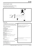
Example
Compressor groupe:
• Refrigerant R404A
• 1 only speed-regulated compressor (30 kW, 30-60 Hz)
• 3 only compressors (15 kW) with working-hour equalisation
• Safety monitoring of each comp frequency converter
• Capacity limitation of compressors via contact signal (load shed-
ding)
• Injection signal to heat exchanger
• Frost protection input (230 V a.c.)
• S4 setting 2°C
Air cooled condenser:
• 4 fans, step regulation
• Pc regulates based on outdoor temperature sensor Sc3
Pumps + defrost:
• start/stop of 2 pumps
• Monitoring via flow switch (contact signal)
• Output for defrost
Receiver:
• Monitoring of liquid level (230 V a.c.)
Fan in plant room
• Thermostat control of fan in engine room ( output)
Safety functions:
• Monitoring of P0, Pc, Sd and superheat in suction line
• P0 min. = -10°C
• Pc max. = 50°C
• Sd max. = 120°C
• SH min. = 5°C, SH max. = 35°C
Other:
• Alarm output used
• External main switch used (contact signal)
Data from this example is used on the next page.
The result is that the following modules should be used:
• AK-CH 650 basic module
• AK-XM 102A digital input module
• AK-XM 204B relay module
• AK-OB 110 analog output module


