Si71-812
Operation
Opration
23
27.
∗
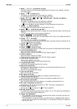
Display “
” “
” “
”
This displays the ventilation mode. (BRC1D527 and so on.) (This is not displayed on the controller
BRC1A62)
28.
∗
Ventilation fan mode selector button (available only connecting the HRV unit)
This is pressed to switch the fan mode of the HRV unit.
29.
∗
Ventilation fan speed control button (available only connecting the HRV unit)
This is pressed to control the fan speed of the HRV unit.
(Refer to item 11)
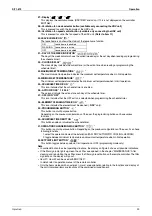
30. LEAVE HOME ICON “
”
The leave home icon shows the status of the leave home function.
31.
∗
DAY OF THE WEEK INDICATOR “
”
The day of the week indicator shows the current week day (or the set day when reading or programming
the schedule timer).
32.
∗
CLOCK DISPLAY “
”
The clock display indicates the current time (or the action time when reading or programming the
schedule timer).
33. MAXIMUM SET TEMPERATURE “
”
The maximum set temperature indicates the maximum set temperature when in limit operation.
34. MINIMUM SET TEMPERATURE “
”
The minimum set temperature indicates the minimum set temperature when in limit operation.
35.
∗
SCHEDULE TIMER ICON “
”
This icon indicates that the schedule timer is enabled.
36.
∗
ACTION ICONS “ 1 2 3 4 5 ”
These icons indicate the actions for each day of the schedule timer.
37.
∗
OFF ICON “OFF”
This icon indicates that the OFF action is selected when programming the schedule timer.
38.
∗
ELEMENT CLEANING TIME ICON “
”
This icon indicates the element must be cleaned ( “
HRV
” only).
39.
∗
PROGRAMMING BUTTON “
”
This button is a multi-purpose button.
Depending on the previous manipulations of the user, the programming button can have various
functions.
40.
∗
SCHEDULE TIMER BUTTON “
”
This button enables or disables the schedule timer.
41. OPERATION CHANGE/MIN-MAX BUTTON “
”
This button is a multi-purpose button. Depending on the previous manipulations of the user, it can have
following functions:
1. select the operation mode of the installation (FAN, DRY, AUTOMATIC, COOLING, HEATING)
2. toggle between minimum temperature and maximum temperature when in limit operation
42. SETPOINT/LIMIT BUTTON “
”
This button toggles between setpoint, limit operation or OFF (programming mode only).
Note
•
In contradistinction to actual operating situations, the display on Figure 3 shows all possible indications.
•
If the filter sign lamp lights up, clean the air filter as explained in the chapter “MAINTENANCE”. After
cleaning and reinstalling the air filter: press the filter sign reset button on the remote controller. The filter
sign lamp on the display will go out.
•
Item 27~ Item 42 can be used with BRC1D527.
In detail, refer to operation manual of the remote controller.
•
Only the items marked with an asterisk (
∗
mark) are explanation relating to the functions and display of
the unit. Unmarked items are functions of the combined air conditioners.
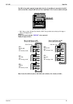
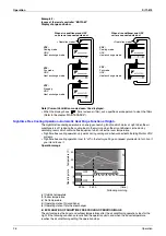
ON
Leave home is enabled
FLASHING
Leave home is active
OFF
Leave home is disabled
Содержание VKM100GAMV1
Страница 9: ...Introduction Si71 812 viii ...
Страница 10: ...Si71 812 General Constructions 1 Part 1 General Constructions 1 General Information 2 1 1 Features 2 ...
Страница 43: ...Operation Si71 812 34 Operation ...
Страница 53: ...Inspection and Maintenance of the Humidifier Si71 812 44 Maintenance ...
Страница 91: ...Troubleshooting Si71 812 82 Troubleshooting ...
Страница 92: ...Si71 812 Field Setting 83 Part 7 Field Setting 1 Field Setting 84 1 1 Field Setting and Test Run 84 ...
Страница 99: ...Appendix Si71 812 90 Appendix 1 Appendix 1 1 Wiring Diagram VKM50GAMV1 VKM80GAMV1 VKM100GAMV1 ...
Страница 100: ...Si71 812 Appendix Appendix 91 VKM50GAV1 VKM80GAV1 VKM100GAV1 ...
Страница 103: ...Piping Diagram Si71 812 94 Appendix ...
Страница 105: ...Si71 812 ii Index ...


