


Operation
Si71-812
16
Operation
[Points to be noted for VKM-GA(M)]
There are following restrictions with VKM-GA(M) model due to its own controlling structure.
1. Stand alone system: No address setting is required because of its automatic addressing function
(corresponding to VRV air conditioner PC-board : Master).
Because it is under a group control, it is always required to connect to a remote controller. The structure
does not permit if no remote controller is connected. A direct connection to a duct is also prohibited.
2. Interlock system : No address setting is required because of its automatic addressing function (Indoor
unit : Master).
•
Basically, the interlocking with an air-conditioner is only made via connection to a remote controller
line (P1, P2).
•
Number of units connectable in case of a remote controller group
Because 2 pieces of controlling PC-board have been built in a VKM-GAM model, count the remote
controller group as : 1 set = 2 units. The maximum number of units connectable to a remote controller
group is 16.
•
External contact point
If you want to start/stop through an external contact point, use external input terminals (T1 and T2).
* If you start/stop using T1 and T2 terminals, the entire remote controller group makes a start/stop.
Note 1) JC/J2 of ventilation PC-board cannot be used. (Because only the ventilation PC-board makes a
start/stop, no synchronized movement with the corresponding VRV indoor unit’s PC-board is
assured.)
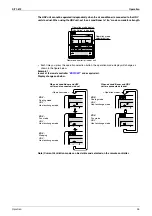
<Example>
How many units of VKM-GAM model can be connected within a single group?
In case of a group composed of (10 × indoor units + VKM-GAM), the maximum number of VKM-GAM is 3.
10 + 3 × 2 = 16 units OK
In case of 4 units ;
10 + 4 × 2 = 18 units NG (2 units are in excess)
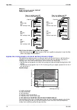
The display and operation of a
remote controller is the same as
a standard indoor unit.
Interlocking of a remote controller group
Содержание VKM100GAMV1
Страница 9: ...Introduction Si71 812 viii ...
Страница 10: ...Si71 812 General Constructions 1 Part 1 General Constructions 1 General Information 2 1 1 Features 2 ...
Страница 43: ...Operation Si71 812 34 Operation ...
Страница 53: ...Inspection and Maintenance of the Humidifier Si71 812 44 Maintenance ...
Страница 91: ...Troubleshooting Si71 812 82 Troubleshooting ...
Страница 92: ...Si71 812 Field Setting 83 Part 7 Field Setting 1 Field Setting 84 1 1 Field Setting and Test Run 84 ...
Страница 99: ...Appendix Si71 812 90 Appendix 1 Appendix 1 1 Wiring Diagram VKM50GAMV1 VKM80GAMV1 VKM100GAMV1 ...
Страница 100: ...Si71 812 Appendix Appendix 91 VKM50GAV1 VKM80GAV1 VKM100GAV1 ...
Страница 103: ...Piping Diagram Si71 812 94 Appendix ...
Страница 105: ...Si71 812 ii Index ...


