background image

20

SERVICING

WARNING

Disconnect ALL power before servicing.

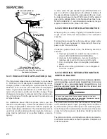
S-200 CHECKING DUCT STATIC

The maximum and minimum allowable external static pres-

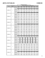
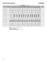
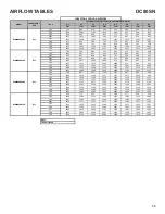
sures  are  found  in  the  specification  section.  These  tables 

also show the amount of air being delivered at a given static 

by a given motor speed or pulley adjustment.

The furnace motor cannot deliver proper air quantities (CFM) 

against statics other than those listed.

Too great of an external static pressure will result in insuffi

-

cient air that can cause excessive temperature rise, resulting 

in limit tripping, etc. Whereas not enough static may result in 

motor overloading.

To determine proper air movement, proceed as follows:

1. 

With clean filters in the furnace, use a draft gauge 

(inclined manometer) to measure the static pressure 

of the return duct at the inlet of the furnace. (Negative 

Pressure)

2. 

Measure the static pressure of the supply duct. (Pos

-

itive Pressure)

3. 

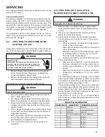
Add the two (2) readings together for total external 

static pressure.

NOTE:  Both readings may be taken simultaneously 

and read directly on the manometer if so desired. If 

an air conditioner coil or Electronic Air Cleaner is 

used in conjunction with the furnace, the readings 

must also include theses components, as shown in 

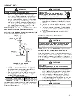
the following drawing.

4. 

Consult proper tables for the quantity of air.

If the total external static pressure exceeds the minimum or 

maximum allowable statics, check for closed dampers, reg

-

isters, undersized and/or oversized poorly laid out duct work.


Amana

Elec tronic  Ai r  Cleaner

    Ca ution 
High Voltage

To a void per sonal in ju ry, wait 15  

secon ds afte r de -ene rgizing u nit

   b efore  touch in g unit  in terior . 

CUTAWAY OF DUCTWORK 
          TO EXPOSE COIL

SUPPLY
    AIR


INCLINED 

MANOMETER

RETURN
    AIR

Checking Static Pressure

(80% Furnace Shown, 90% Similar)

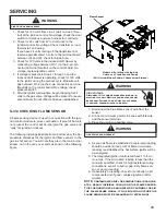
S-201 CHECKING TEMPERATURE RISE

The  more  air  (CFM)  being  delivered  through  a  given  fur

-

nace, the less the rise will be; so the less air (CFM) being 

delivered, the greater the rise. The temperature rise should 

be adjusted in accordance to a given furnace specifications 

and its external static pressure. An incorrect temperature 

rise may result in condensing in or overheating of the heat 

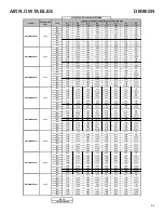
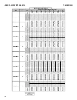
exchanger. An airflow and temperature rise table is provided 

in the blower performance specification section. Determine 

and adjust temperature rise as follows:

1. 

Operate furnace with burners firing for approximately 

ten minutes. Check BTU input to furnace - do not ex

-

ceed input rating stamped on rating plate. Ensure all 
registers are open and all duct dampers are in their 

final (fully or partially open) position.

2.  Place thermometers in the return and supply ducts as 

close to the furnace as possible. Thermometers must 

not be influenced by radiant heat by being able to 

“see” the heat exchanger.

Содержание DM80SN

Страница 1: ...anual only licensed personnel should service the equipment Improper installation adjustment servicing or repair of the equipment specified in this manual or attempting to install adjust service or rep...

Страница 2: ...EVIEW ALL SERVICE INFORMATION IN THE APPROPRIATE SERVICE MANUAL BEFORE BEGINNING REPAIRS IMPORTANT NOTICES RECOGNIZE SAFETY SYMBOLS WORDS AND LABELS WARNING This unit should not be connected to or use...

Страница 3: ...Installation and service must be performed by a qualified installer service agency or the gas supplier IMPORTANT INFORMATION WARNING Should overheating occur or the gas supply fail to shut off turn of...

Страница 4: ...rcular a trav s del aparato cuando se opera en cualquier modo B10259 216 CO can cause serious illness including permanent brain damage or death B10259 216 RISQUE D EMPOISONNEMENT AU MONOXYDE DE CARBON...

Страница 5: ...itial Release B 1st Revision Configuration M Upflow Horizontal Major Revision C Downflow Horizontal A Initial Release B 1st Revision Nox AFUE 80 80 AFUE 92 92 AFUE 96 96 AFUE 97 97 AFUE Cabinet Width...

Страница 6: ...cause death or serious illness and which are known to the state of California to cause cancer birth defects or other reproductive harm This product contains fiberglass insulation Fiberglass insulatio...

Страница 7: ...grounded object Product Application This product is designed for use as a residential home gas furnace It is not designed or certified for use in mobile home trailer or recreational vehicle applicatio...

Страница 8: ...ating Inlet gas supply pressures must be maintained within the ranges specified below The supply pressure must be con stant and available with all other household gas fired appli ances operating The m...

Страница 9: ...ted beside the low voltage thermostat connection strip Twinning allows simultaneous operation of two furnaces and forces the indoor blower motors of each furnace to oper ate synchronously into a commo...

Страница 10: ...is is a 24 volt circuit only the common con nection must be on C terminal of the low voltage terminal strip where thermostat wires are con nected Wiring for this circuit must NOT be con nected to the...

Страница 11: ...s the available speeds for Low High heat mode 3 When the center switch is pressed the current displayed speed shall be selected and control shall apply the newly selected speed in next heating call NO...

Страница 12: ...rtment door and move the furnace gas valve manual control to the OFF position 3 Close the manual gas shutoff valve external to the furnace 4 Replace the burner compartment door Filters Filters must be...

Страница 13: ...e then should be wired to the furnace accordingly CHECKING FOR PHASING PRIMARY TO SECONDARY OF UNMARKED TRANSFORMERS VOLT OHM METER G ND PRIMARY SECONDARY TRANSFORMER R C METER READS 24 VOLTS LINE VOL...

Страница 14: ...ormance Filters should be cleaned permanent or replaced disposable every two months or as required It is the owner s responsibility to keep air filters clean When replacing a filter it must be replace...

Страница 15: ...the unit adjust the gas valve pressure regulator or resize orifices CAUTION Always connect a manometer to the outlet tap at the gas valve before adjusting the pressure regulator In no case should the...

Страница 16: ...79 947 45 20 40 80 160 400 20 45 90 180 360 900 46 78 157 391 21 43 86 171 343 857 47 19 38 76 153 383 22 41 82 164 327 818 48 75 150 375 23 39 78 157 313 783 49 147 367 24 37 75 150 300 750 50 18 36...

Страница 17: ...CHECKING AUXILIARY LIMIT CONTROL 22 S 302 CHECKING FLAME ROLLOUT CONTROL 22 S 303 INDUCED DRAFT BLOWER MOTOR 23 S 304 CHECKING GAS VALVE REDUNDANT 23 S 305 CHECKING MAIN BURNERS 24 S 306 CHECKING ORI...

Страница 18: ...ced replace with AWM 105 C 2 64 thick insulation of the same gauge or its equivalent CHECKING THERMOSTAT WIRING AND ANTICIPATOR S 3A THERMOSTAT AND WIRING WARNING Disconnect ALL power before servicing...

Страница 19: ...r completing check and or replacement of trans former and check and or repair of control circuit reinstall blower compartment door 8 Turn on electrical power and verify proper unit operation S 16 CHEC...

Страница 20: ...es for the quantity of air If the total external static pressure exceeds the minimum or maximum allowable statics check for closed dampers reg isters undersized and or oversized poorly laid out duct w...

Страница 21: ...0 CHECKING PRIMARY LIMIT CONTROL All use a nonadjustable automatic reset bi metal type limit control Refer to the following drawing for the location of the primary limit Location of Primary Limit Prim...

Страница 22: ...sonal injury or death VOLT OHM METER RED RESET BUTTON COLOR IDENTIFYING TAB Testing Auxiliary Limit Control WARNING To avoid possible fire only reset the auxiliary limit control once If it should open...

Страница 23: ...regulation and 100 percent safety shut off WARNING Disconnect ALL power before servicing Single stage gas valves should be tested on the furnace with 24 VAC connected to the gas valve and manometers r...

Страница 24: ...er to prevent distortion In no instance should an orifice be peened over and redrilled This will change the angle or deflection of the vacuum effect or entraining of primary air which will make it dif...

Страница 25: ...er before servicing or in stalling this unit Multiple power sources may be present Failure to do so may cause proper ty damage personal injury or death 5 Disconnect manometer after turning off gas at...

Страница 26: ...ve the outlet pressure boss plug Install an 1 8 NPT hose barb fitting into the outlet pressure tap b Attach a hose and manometer to the outlet pres sure barb fitting c Turn ON the gas supply d Turn on...

Страница 27: ...rature the igniter ohm reading should be from 37 68 ohms S 309 CHECKING FOR FLASHBACK Flashback will also cause burning in the burner venturi but is caused by the burning speed being greater than the...

Страница 28: ...SI Z223 1 and information provided by the gas supplier to determine the proper orifice size S 312 CHECKING FOR DELAYED IGNITION Delayed ignition is a delay in lighting a combustible mixture of gas and...

Страница 29: ...out The following drawings illustrate from a bottom view the ap proximate distances for the ignitor and flame sensor to the gas in shot burner You will note they are in the main burner stream not in t...

Страница 30: ...80SN0803B 0 70 0 06 0 85 0130F00505 DM80SN0804B 0 70 0 06 0 85 0130F00505 DM80SN0805C 0 75 0 07 0 90 0130F00506 DM80SN1005C 0 70 0 06 0 85 0130F00505 DM80SN1205D 0 80 0 05 0 95 0130F00507 DC80SN0403A...

Страница 31: ...67 315 N A F02 1141 1089 1045 1001 958 914 869 823 F03 1311 1267 1226 1189 1150 1114 1072 1034 F04 1395 1347 1309 1270 1233 1199 1164 1125 F05 1490 1447 1407 1373 1336 1303 1269 1237 F06 1553 1510 146...

Страница 32: ...22 439 367 315 N A F02 1141 1089 1045 1001 958 914 869 823 F03 1311 1267 1226 1189 1150 1114 1072 1034 F04 1395 1347 1309 1270 1233 1199 1164 1125 F05 1490 1447 1407 1373 1336 1303 1269 1237 F06 1553...

Страница 33: ...F01 841 657 595 522 439 367 315 N A F02 1141 1089 1045 1001 958 914 869 823 F03 1311 1267 1226 1189 1150 1114 1072 1034 F04 1395 1347 1309 1270 1233 1199 1164 1125 F05 1490 1447 1407 1373 1336 1303 12...

Страница 34: ...2 1141 52 1089 54 1045 57 1001 59 958 62 914 869 823 F03 1311 45 1267 47 1226 48 1189 50 1150 52 1114 1072 1034 F04 1395 42 1347 44 1309 45 1270 47 1233 48 1199 1164 1125 F01 837 N A 752 N A 671 N A 5...

Страница 35: ...62 1233 1207 F01 760 697 636 569 481 402 349 300 F02 1286 1238 1196 1157 1117 1077 1036 998 F03 1393 1348 1308 1270 1230 1196 1158 1123 F04 1459 1414 1371 1336 1297 1264 1229 1193 F05 1753 1713 1677 1...

Страница 36: ...1262 1233 1207 F01 760 697 636 569 481 402 349 300 F02 1286 1238 1196 1157 1117 1077 1036 998 F03 1393 1348 1308 1270 1230 1196 1158 1123 F04 1459 1414 1371 1336 1297 1264 1229 1193 F05 1753 1713 167...

Страница 37: ...1348 1318 1289 1262 1233 1207 F01 760 697 636 569 481 402 349 300 F02 1286 1238 1196 1157 1117 1077 1036 998 F03 1393 1348 1308 1270 1230 1196 1158 1123 F04 1459 1414 1371 1336 1297 1264 1229 1193 F0...

Страница 38: ...A 697 N A 636 N A 569 N A 481 N A 402 349 300 F02 1286 46 1238 48 1196 50 1157 51 1117 53 1077 1036 998 F03 1393 43 1348 44 1308 45 1270 47 1230 48 1196 1158 1123 F04 1459 41 1414 42 1371 43 1336 44 1...

Страница 39: ...set at 7 Secs Adjustments can be made in 7 Secs increments from0 to 35 Secs Cool Off Delay Delay Seconds Default set at 65 Secs Adjustments can be made in 5 Secs increments from 0 to 120 Secs Blower...

Страница 40: ...1 STAGE STATUS CODES 40 Idle Continous Fan F Compressor Cooling Low Stage Compressor Cooling High Stage Gas heat Single Stage Control OEM test Mode Mode Main Menu STATUS MENU...

Страница 41: ...ulator blower motor Correct speed or replace blower motor if necessary Loose or improperly connected wiring in high limit circuit Tighten or correct wiring connection Flame sensed with no call for hea...

Страница 42: ...ontrol module Blown fuse or tripped circuit breaker Correct condition which caused fuse to open replace fuse Integrated control module is non functional Replace non functional integrated control modul...

Страница 43: ...PERATURE RATING OF AT LEAST 105v C USE COPPER CONDUCTORS ONLY 4 UNIT MUST BE PERMANENTLY GROUNDED AND CONFORM TO N E C AND LOCAL CODES 5 TO RECALL THE LAST 6 FAULTS MOST RECENT TO LEAST RECENT DEPRESS...

Страница 44: ...is very interested in all product comments Please fill out the feedback form on the following link https daikincomfort com contact us You can also scan the QR code on the right to be directed to the f...

Отзывы: