background image

INSTALLATION, OPERATING

and

SERVICE MANUAL

NEWMAC COMBINATION FURNACE

CL 86-96C, CL 86-96G, CL 115-170C, CL 115-170G 

The installation of the unit shall be in accordance with the 

regulations of the authorities having jurisdiction.

HEAD OFFICE

MARKETING / PRODUCTION

Newmac Mfg. Inc.

DEBERT AIR INDUSTRIAL PARK,


LANCASTER CRESCENT

P.O. BOX 9, DEBERT

NOVA SCOTIA, BOM 1G0

PHONE: 902-662-3840

FAX:       902-662-2581

WAREHOUSE

Newmac Mfg. Inc.

430  SPRINGBANK AVE., SOUTH

P.O. BOX 545

WOODSTOCK, ONTARIO

N4S 7Y5

PHONE: 519-539-6147

FAX:       519-539-0048

EMAIL: 

[email protected]

HOMEPAGE: newmacfurnaces.com

NOTICE TO HOMEOWNER:

READ THESE INSTRUCTIONS

SAVE THESE INSTRUCTIONS

2210040 Revised April 2007

Printed:__________

Содержание CL 115-170C

Страница 1: ...TING PRODUCTION Newmac Mfg Inc DEBERT AIR INDUSTRIAL PARK LANCASTER CRESCENT P O BOX 9 DEBERT NOVA SCOTIA BOM 1G0 PHONE 902 662 3840 FAX 902 662 2581 WAREHOUSE Newmac Mfg Inc 430 SPRINGBANK AVE SOUTH...

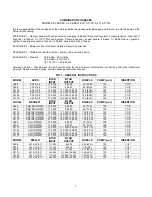
Страница 2: ...00 111 000 109 000 1 00 80 R 100 7 7 8 CL140 F AFC 3 8 175 000 140 000 138 000 1 25 80 R 100 7 7 8 CL155 F AFC 3 8 189 000 152 000 150 000 1 35 80 R 100 7 7 8 CL170 F AFC 3 8 210 000 169 000 168 000 1...

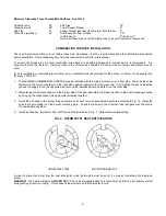
Страница 3: ...air on either side The units leave the factory with the return or cold air on the right when viewed looking at the oil burner end If it simplifies the duct installation to have the supply air on the o...

Страница 4: ...the regulations of the local authorities having jurisdiction with the applicable Electrical Code and C S A Standard B139 The Installation Code for Oil Burning Appliances and Equipment and with the reg...

Страница 5: ...than 24 inches high increase the duct size proportionately The Supply Air free area for CL 115 C G is the same as CL 140 C G because the wood burning portion of the furnace can produce 140 000 BTU HUM...

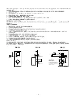
Страница 6: ...ly pull the sensor to one side 5 Using a suitable soft brush or cloth carefully clean any soot from the surface of the sensor and the inside of the 5 8 diameter tube 6 Replace the sensor and secure wi...

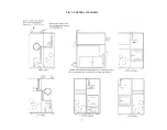
Страница 7: ...6 FIG 6 FLUE PIPE CONNECTION MINIMUM INSTALLATION CLEARANCES...

Страница 8: ...7 FIG 7 CONTROL LOCATIONS...

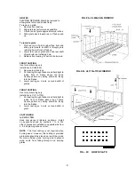
Страница 9: ...8 FIG 8A COMBINATION MODELS CL 115C 170C FIREBOX INSTALLATION PROCEDURE WITH STAINLESS STEEL FRONT FIG 8B COMBINATION MODELS CL86C 96C FIREBOX INSTALLATION PROCEDURE WITH STAINLESS STEEL FRONT...

Страница 10: ...ove the brick Square pattern on casting should be facing into the firebox 3 Lower casting so it rests on round shaft of grates FRONT CASTING Use for coal burning only Installation in CL115 170G 1 Put...

Страница 11: ...in accomplished by speeding up or slowing down the fan by means of the adjustable pulley on the fan motor Maximum temperature rise is 85 o F on models CL 115 170 and 75 o F on CL 86 96 The fan speed...

Страница 12: ...ould be kept at least one quarter full Outside underground storage tanks if not equipped with a special gauge are gauged by stick Recommended grade of fuel No 2 Furnace Oil CAUTION 1 DO NOT USE GASOLI...

Страница 13: ...reloading the firebox there will be a build up of ash and coals from the previous fire Rake the coals mixed with ash to the front of the firebox which places the coals at the front Throw in your wood...

Страница 14: ...should only be done only with a hot fire Shaking should be done at least once a day but not more than twice a day Best results from shaking will occur if short chopping strokes are used rather than l...

Страница 15: ...chimney on a rope Work the brush up and down the chimney to scrape the accumulated creosote and soot off the chimney walls Remove the residue from the cleanout at the base of the chimney SEMI ANNUALLY...

Страница 16: ...her unit unless the damper is in the full heat or cool position Adequate means shall be provided for the disposal of condensate and to prevent dripping of condensate on the heating element 4 1 5 2 Fur...

Страница 17: ...nimum supply duct free area of 180 square inches must be maintained at all times during heating the cycle A minimum return duct free area of 250 square inches must be maintained at all times during he...

Страница 18: ...17 FIG 10 TYPICAL A C COIL INSTALLATION...

Страница 19: ...18 FIG 11 WIRING DIAGRAM WITH AIR CONDITIONING...

Страница 20: ...19 FIG 12 CL SERIES WIRING DIAGRAM...

Страница 21: ...20 FIG 13 COMBINATION AIR FLOW FIG 14 AIR CONDITIONING INSTALLATION...

Страница 22: ...5D BURNER INSERTION RIELLO SLEEVE POSITION FIG 15E DIMENSIONAL RELATIONSHIPS FIG 15A 15D AERO BECKETT RIELLO A 1 8 5 32 B 7 16 13 64 C 1 16 5 64 to 7 64 Z 1 3 8 E 7 7 8 7 1 2 Z A B C E Insertion to fl...

Страница 23: ...operate at 3 0 W C for natural gas and 3 5 W C for propane gas Adams Gas Burner Model HP 2258 PS must operate at 3 5 W C for natural gas and 11 0 W C for propane gas LP burners are designated by LP Ex...

Страница 24: ...Prop 3215 015 5 Ignition System EPI 100 or EPI 6 Transformer 20 V A AT 20 A 7 Relay R 8222 A 1002 8 Terminal Block 7586 3 9 Air Door 7582 A 10 Bottom Access Door 7587 B 11 Slide Tray Assembly 7586 D...

Страница 25: ...5152016 10 Raceway 2726202550 11 Air Band Assembly 2726200100 12 Ignition Control 9035061311 13 Wiring Harness not shown 9035061321 14 High Voltage Cable 9035061301 15 Fan Center 9035061210 16 Fuse As...

Страница 26: ...25 FIG 16 1G THERMO DISC MOUNTING ON BURNER PLATE...

Страница 27: ...31100 14 Electrode with porcelains 2725132100 2090004 ITEM DESCRIPTION AERO PART NEWMAC PART 14A Bus bars specify length 15 Turbo static disc F AFC 3 2725353000 16 Jam hex nut 9935193401 17 Knurled lo...

Страница 28: ...wer Wheel 16A 7456U 2090069 X X Primary Relay Honeywell R7184B 16B 7457U 2090067 Primary Relay Honeywell R7184P 17 5770 X X Junction Box Kit 18 51771U 2090064 X X Electronic Ignitor 14 000 Volt 20 700...

Страница 29: ...mp cover 19 3002279 X X Solenoid Coil 20 3007802 2060007 X X Pump 22 3005843 X X Motor 25 3001157 2010048 X X Primary control 530 SE C 26 3002280 2010045 X X Photo cell 28 3005855 X X Universal mounti...

Страница 30: ...Brick Loc 5 5300012 Slide Plate Assembly 19 4060114 Firedoor Air Chute 6 2180003 Filter 20 X 25 X 1 20 2080009 Front Gasket 7 5300007 Firedoor Gasket Set 21 4120116 Furnace Section Front Panel 8 5300...

Страница 31: ...lide Plate Assembly 19 4060171 Firedoor Air Chute 6 2180002 Filter 16 X 25 X 1 20 5110006 Split Brick 1 X 4 X 9 Box of 6 7 5300005 Firedoor Gasket Set 21 2080001 Front Gasket 8 5300009 Firedoor Handle...

Страница 32: ...009 Cast Liner 6 2180003 Filter 20 X 25 X 1 20 2030001 Corbel Combustion Chamber 7 5300003 Firedoor Ashdoor Set Complete 21 2080020 Front Gasket 8 5300007 Firedoor Gasket Set Complete 22 4120117 Furna...

Страница 33: ...Filter 16 X 25 X 1 20 2030004 Corbel Combustion Chamber 7 5300004 Firedoor Ashdoor Set Complete 21 4060106 Brick Loc 8 5300005 Firedoor Gasket Set Complete 22 2080016 Front Gasket 9 4120323 Blower Se...

Страница 34: ...when they are freshly cut The popular hardwoods have moisture contents of about 45 percent Air dried wood has a moisture content of about 15 percent and kiln dried wood may have a moisture content of...

Страница 35: ...almost anywhere in a wood heating system from the top of the chimney to the insides of the cover itself Creosote which remains in a chimney after its initial formation may later be significantly modi...

Страница 36: ...when the fire is hot it will be burned Chimney fires occur when the combustible deposits on the inside of a chimney burn The deposits may be raw creosote pyrolyzed creosote or soot Ignition requires a...

Страница 37: ...artially used for combustion A carefully designed fireplace makes use of perhaps 10 15 of the heat available most still going up the flue The well constructed potbellies get perhaps 20 25 and the auto...

Страница 38: ...r fall when temperatures are mild This will cause the unit to be shut down for extended periods at a time and will form creosote and soot c In the Multifuel units two or three times a week burn the oi...

Страница 39: ...E 8 CONTACT SERVICE PERSONNEL FOR AIR FILTER REPLACEMENT 9 CONTACT SERVICE PERSONNEL BEFORE AND AFTER EXTENDED PERIODS OF APPLIANCE INOPERATION 10 THE BURNER IS FULLY AUTOMATIC IN OPERATION ALL ADJUST...

Страница 40: ...NSTALLATION DATE ______________________________ DATE 1 FUEL INPUT GPH 2 FUEL PRESSURE PSIG 3 DRAFT BREECH 4 DRAFT OVERFIRE 5 NOZZLE ANGLE PATTERN 6 CO2 PERCENT 7 BURNER MODEL 8 FLUE GAS TEMP 0 F 9 ROO...

Страница 41: ...e heating unit must not be modified away from its published design and or specifications without prior written authorization for such modification from Newmac 4 The heating unit must be correctly size...

Отзывы: