


User's Manual
41
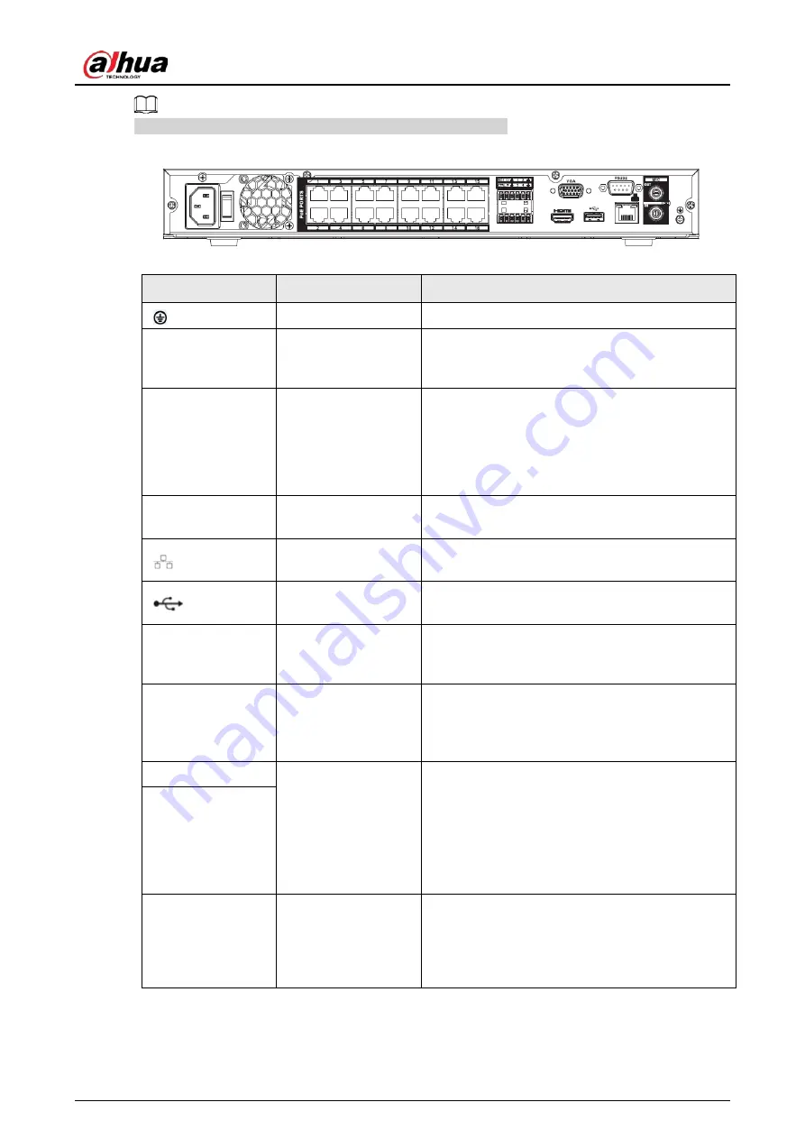
The figure is for reference only. The actual product shall prevail.
Figure 2-62 Rear panel
Table 2-30 Ports
Port Name
Connection
Function
GND
Ground end.
MIC IN
Audio input port
Bidirectional talk input port. It is to receive the
analog audio signal output from the devices such
as microphone, pickup.
MIC OUT
Audio output port
Audio output port. It is to output the analog
audio signal to the devices such as the sound box.
●
Bidirectional talk output.
●
Audio output on 1-window video monitor.
●
Audio output on 1-window video playback.
RS232
RS232 debug COM
It is for general COM debug to configure IP
address or transfer transparent COM data.
Network port
10M/100Mbps self-adaptive Ethernet port.
Connect to the network cable.
USB port
USB port. Connect to mouse, USB storage device
and etc.
VGA
VGA video output
port
VGA video output port. Output analog video
signal. It can connect to the monitor to view
analog video.
HDMI
High Definition
Media Interface
High definition audio and video signal output
port. It transmits uncompressed high definition
video and multiple-channel data to the HDMI port
of the display device. HDMI version is 1.4.
NO1
Alarm output port
●
1 group of alarm output ports. (port NO1–C1).
Output alarm signal to the alarm device.
Please make sure there is power to the
external alarm device.
●
NO: Normal open alarm output port.
●
C: Alarm output public end.
C1
CTRL
—
Controllable power supply output. Control the
output of the on-off button alarm relay. It controls
the alarm device with the presence or absence of
voltage. It can also be used as power input for
some alarm devices such as alarm detectors.
Содержание NVR41-4KS2 Series
Страница 1: ...Dahua Network Video Recorder User s Manual ZHEJIANG DAHUA VISION TECHNOLOGY CO LTD V1 1 0 ...
Страница 74: ...User s Manual 58 Figure 2 79 Alarm input port Figure 2 80 Alarm input port ...
Страница 101: ...User s Manual 85 Figure 3 41 Step 9 Secure the HDD bracket and put the top cover back ...
Страница 114: ...User s Manual 98 3 6 15 NVR616 4KS2 Series The following figure is for reference only Figure 3 58 ...
Страница 132: ...User s Manual 116 Figure 4 19 Modify IP Step 3 Set parameters See Table 4 5 ...
Страница 147: ...User s Manual 131 Figure 4 29 Period Step 3 Set record type See Figure 4 30 ...
Страница 319: ...User s Manual 303 The Exception interface is displayed See Figure 4 190 Figure 4 190 Figure 4 191 Figure 4 192 ...
Страница 420: ...User s Manual 404 Figure 4 290 File management Step 2 Click Add The Add interface is displayed See Figure 4 291 ...
Страница 452: ...User s Manual ...


