connections that have even a moderate outdoor line build out. A good rule of thumb is
that all lines entering or exiting a building need protection. Both ends of the cables
between buildings must be protected! See section 5.2 for detailed specifications and
usage information on
optional
primary lightning protection available from Carlson
Wireless.
2.1.3
2.1.4
Line of Sight
Visual line of sight is the straight, unobstructed line between the Base unit’s antenna and
the CPE’s antenna. In other words, when you look from one antenna you can see the
other one. Because RF waves do not travel in a narrow beam, but spread out as they
travel through space, simple line of sight is
not adequate
for a microwave path. As the
waves travel out from the transmitting antenna, the signal density decreases and more
area around the visual LOS is necessary to be able to receive a reasonable signal at the
receiving antenna. This three dimensional space is called the RF line of sight and is
described by Fresnel zones named after the French physicist who first discovered their
importance.
Fresnel Zone
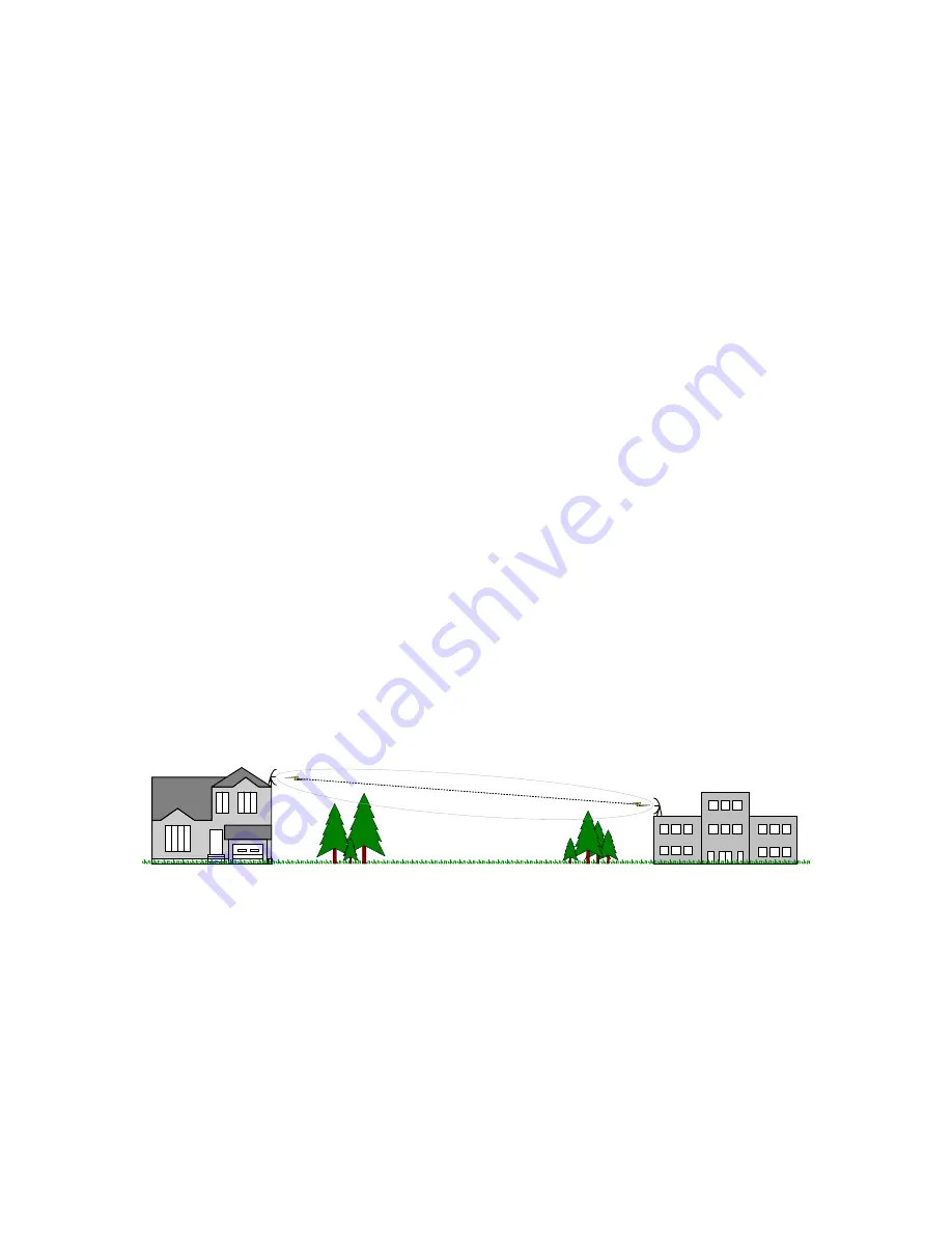
The first Fresnel Zone is the football shaped volume area, around the line-of-sight, that
radio waves spread into after they leave the antenna.
Trees, buildings, mountains and any number of other objects can occupy the Fresnel
Zone. The curvature of the earth, even for some short paths, also tends to put the
ground into the Fresnel Zone. These objects can either reflect or absorb the signal
traveling between antennas. A rule of thumb is that the center
(60% of the first Fresnel
Zone) must be free of any obstruction for tolerable attenuation of the signal.
It is
better to have the first Fresnel zone entirely clear of any objects. For paths over water, it
is recommended that the entire first Fresnel Zone be clear to eliminate fading from the
strong out-of-phase reflections off the surface of the water.
Figure 1: Line of Sight is clear, the first Fresnel Zone is NOT clear. This path will
experience significant outages.
2.1.5 Path Loss
After confirming line of sight and adequate Fresnel Zone clearance, add the Free Space
Loss of the radio signal, RF cable losses and antenna gains to determine your system’s
remaining signal, i.e. fade margin. The chart below shows various antenna and distance
combinations.
Trailblazer Installation and User Manual
6


