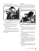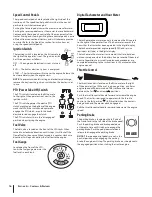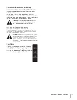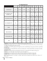
Controls & Features
4
15
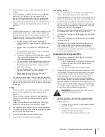
Figure 4-1
E
F
1/4 1/2
L.P.
GAS
FUEL
OK
OK
DD
A
V E
R
T I C A
L
H
O
R
I Z O N TA
L
Fuel
Valve
Fuel
Gauge
Relief
Valve
Valve
Fill
AVOID SERIOUS INJURY OR DEATH
• READ THE OPERATOR'S MANUAL, BEFORE USING THE MACHINE.
• GO ACROSS, NOT UP AND DOWN SLOPES.
• IF MACHINE STOPS GOING UPHILL, STOP BLADES AND BACK DOWN SLOWLY.
• AVOID SUDDEN TURNS.
• DO NOT MOW WHEN CHILDREN OR OTHERS ARE AROUND.
• NEVER CARRY CHILDREN EVEN WITH BLADES OFF.
• KEEP SAFETY DEVICES (GUARDS, SHIELDS, SWITCHES, ETC.)
IN PLACE AND WORKING.
• LOOK DOWN AND BEHIND BEFORE AND WHILE BACKING.
• REMOVE OBJECTS THAT COULD BE THROWN BY THE BLADES.
• DO NOT OPERATE UNIT WHERE IT COULD SLIP OR TIP.
• KNOW LOCATION AND FUNCTION OF ALL CONTROLS.
• BE SURE BLADES AND ENGINE ARE STOPPED BEFORE PLACING HANDS
OR FEET NEAR BLADES.
• BEFORE LEAVING OPERATOR POSITION, DISENGAGE BLADES, LET SPEED PEDAL
RETURN TO NEUTRAL, ENGAGE PARKING BRAKE, SHUT OFF AND REMOVE KEY.
• WHEN USING THE OPTIONAL GRASS BAGGING ATTACHMENT, THE FRONT
COUNTER WEIGHT INCLUDED WITH BAGGER MUST BE INSTALLED.
• DO NOT ADD FUEL WHILE THE ENGINE IS HOT OR RUNNING.
• STOP ENGINE, DISCONNECT SPARK PLUG(S) BEFORE ADJUSTING OR
SERVICING.
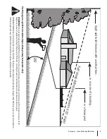
• SLOW DOWN AND USE CAUTION ON SLOPES, 15º DEGREES MAX.
P
U
S
H
T
O
L
O
C
K
,
P
U
S
H
T
O
R
E
L
E
A
S
E
P
U
S
H
T
O
S
T
O
P
BR
AK
E
IMPLEMENT LIFT
Deck Height
Index
Ignition
Switch
FA
S
T
S
L
OW
O
F
F
R
U
N
S
T
A
R
T
•
SECURELY FASTEN
YOUR SEAT BELT
B EFORE USE.
•
ALWAYS WEAR THE
SEAT BELT WHEN THE
ROPS IS LOCKED IN
PLACE UPRIGHT.
•
DO NOT WEAR SEAT BELT WHEN ROPS IS DOWN, I.E. NOT
L OCKED UPRIGHT.
•
DO NOT MODIFY, REPAIR, OR REMOVE ANY ROPS
COMPONENTS INCLUDING SEAT BELTS.
•
WHERE POSSIBLE, AVOID OPERATING THE MACHINE NEAR
DITCHES, EMBANKMENTS, AND HOLES.
•
REDUCE SPEED WHEN
T URNING, OPERATING
ON SLOPES, AND ON
ROUGH, SLICK, OR
M UDDY SURFACES.
•
STAY OFF SLOPES
T OO STEEP FOR
SAFE OPERATION.
•
WATCH WHERE YOU ARE GOING, ESPECIAL LY ON SLOPES, WHEN
T URNING, AND MANEUVERING AROUND OR UNDERNEATH OBSTACLES
STARTING INSTRUCTIONS
•
To START, PARK BRAKE must be set, push down to latch.
•
P.T.O. switch in OFF (down) position.
•
Foot pedals in NEUTRAL.
•
Throttle set properly, CHOKE position if "cold".
•
Turn key to ON, then START, release when engine runs.
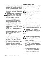
THIS MACHINE IS EQUIPPED WITH A ROLL
OVER PROTECTIVE SYSTEM (ROPS)
FO
RW
AR
D
F
R
RE
VE
RS
E
Throttle Control
PTO Switch
Tachometer/
Hour Meter
Cup Holder
Reverse Speed
Control Pedal
Forward Speed
Control Pedal
Brake Pedal/
Parking Brake
Power
Implement
Lift
Roll-Over
Protection
System
NOTE:
References to LEFT, RIGHT, FROnT, and REAR indicate that
position on the tractor when facing forward while seated in the
operator’s seat.
Deck Height Index
The deck height index consists of several holes located on the
front/right of the foot platform. Each hole corresponds to a 1⁄
4”
change in the deck height position ranging from 1”
at the lowest
notch to 5” at the highest notch.
Cup Holder
The cup holder is located toward the rear of the LH console to
the left of the operator’s seat.
Power Implement Lift
The power implement lift is located on the LH console to the left
of the operator’s seat, and is used to raise and lower the mower
deck.
To raise the mowing deck to the transport position, place the
clevis pin on the deck height index in the furthest hole from
you and secure with the cotter pin and then use the power
implement lift. To lower the deck, remove the clevis pin and
reinsert it in the desired cutting height and secure with cotter pin
and then use the power implement lift.
Seat Adjustment Levers (Not Shown)
The levers allow for adjustment of the operator’s seat. Refer to
the Assembly & Set-Up section for instructions on adjusting the
seat.
Содержание Tank S S7237
Страница 45: ...Notes 12 45 ...


