


13
s
ectiOn
2 — a
sseMbly
& s
et
-u
p
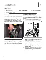
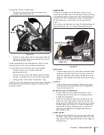
To adjust the tilt of the steering wheel:
Pull back on the adjustment lock lever to loosen the
1.
steering wheel tilt. See Fig. 3-10.
Place the steering wheel in the desired angle and lock into
2.
place by pushing the adjustment lock lever forward until
the steering wheel is secure.
Proper steering column and seat adjustment will result in the
following (to adjust the seat see Suspension Seat below):
In the neutral position with hands on the steering wheel,
Operator’s upper arms should be relaxed and
•
approximately vertical.
Operator’s forearms should be approximately horizontal.
•
Operator’s back should stay in contact with the seat back.
•
Steering column should not contact operator’s legs.
•
Check the results of any adjustments to the conditions described
above. Repeat any adjustment procedures as required until all
conditions are met.
Loosen
Tighten
Figure 3-10
Suspension Seat
This tractor is equipped with an adjustable suspension seat
system, which includes a seat with retractable seat belt assembly,
a low profile mechanical suspension, and an Operator Presence
Sensor (OPS). The OPS in the form of a switch, is integrated into
the seat bottom and is connected to the machine electrical
system.
The seat has several adjustments to meet the individual needs of
the operator. Refer to Fig. 3-11 for the following adjustments.
Seat Position
To adjust the position of the seat, pull forward and hold the
1.
seat adjustment lever. Slide the seat forward or rearward
to the desired position; then release the adjustment lever.
Make sure seat is locked into position before operating the
tractor.
Arm Rests
To adjust to the arm rest rotate the roller bearing, single-
1.
locking knob on the bottom of the arm. The angle of the
arm can move up or down.
Mechanical Suspension Mechanism
To adjust the mechanical suspension mechanism, there
1.
is a lever on the front of the seat with an orange colored
indicator arrow and guage.
Sit down in the operator’s position and look down at the
2.
center of the seat, flip the lever out towards the right and
pull upward on the fold-out lever and “pump up” to increase
seat load capacity and firmness. Push the lever downward
to reduce the firmness and load capacity. Just center the
orange-colored indicator on the guage to achieve your
exact weight setting.
Lumbar Support
The knob on the back left of the operator’s seat can change
1.
the lumbar support from the top portion of the seat, to the
lower portion and off. Rotate the knob to set the support to
the desired area.
Seat Adjustment
Lever
Mechanical Suspension
Mechanism
Lumbar
Support
Knob
Arm Rest
Adjustments
Figure 3-11
Содержание Tank S S7237
Страница 45: ...Notes 12 45 ...


