52
Item
No.
Description
Part No.
Quantity
16H-340
16H-410
16H-460
16H-505
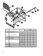
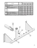
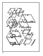
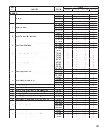
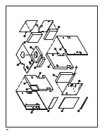
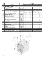
3. Base Assembly
3A
Base End Panel
260660
2
2
2
2
3B
Base Channel Assembly
260647
2
---
---
---
260648
---
2
---
---
260649
---
---
2
---
260650
---
---
---
2
3C
Base Rear Panel Assembly
260667
1
---
---
---
260668
---
1
---
---
260669
---
---
1
---
260670
---
---
---
1
3D
Base Front Panel Assembly
260607
1
---
---
---
260608
---
1
---
---
260609
---
---
1
---
260610
---
---
---
1
3E
Burner Access Panel Assembly
260627
1
---
---
---
260628
---
2
---
---
260629
---
---
2
---
260630
---
---
---
2
3F
Jacket Attachment Bracket
7041601
4
4
4
4
3G
Bolt, Carriage, ¼ - 20 x 1¼”
Procure Locally
4
4
4
4
3H
Washer, ¼” Flat
Procure Locally
4
4
4
4
3J
Nut, ¼ - 20
Procure Locally
4
4
4
4
3K
Screw, Self Tapping, ¼ - 20 x ½”
Procure Locally
4
5
5
6
3L
Screw, Cap, Hex Head, 5/16” - 18 x ¾”
Procure Locally
2
2
2
2
3M
Screw, Cap, Hex Head, 5/16 - 18 x 1¼”
Procure Locally
6
6
6
6
3N
Screw, Sheet Metal, #8 x ½”
Procure Locally
8
8
8
8
3P
Washer, 3/8” Flat
Procure Locally
6
6
6
6
3Q
Nut, 5/16”
Procure Locally
6
6
6
6
3R
Screw, Self Tapping, ¼ - 20 x ¾”
Procure Locally
10
10
10
10
Содержание 16H-340
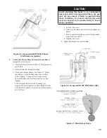
Страница 11: ...11 Figure 6 Flame Roll out Switch Installation Figure 7 Burner Burner Access Panel Installation ...
Страница 13: ...13 Figure 8 Jacket Assembly ...
Страница 14: ...14 Figure 9 EP CSD 1 Control Installation ...
Страница 16: ...16 Figure 11 Main Gas Piping Intermittent Ignition EI ...
Страница 17: ...17 Figure 12 Schematic Pilot Piping Honeywell EI USA ...
Страница 18: ...18 Figure 15 Schematic Gas Piping EP CSD 1 Control System 16H 410 16H 505 ...
Страница 31: ...31 Figure 31 Wiring Diagram Honeywell EI USA Intermittent Circulation 16H 340 16H 510 MegaStor Relay MegaStor ...
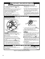
Страница 37: ...37 Figure 41 Operating Instructions EI ...
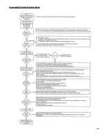
Страница 47: ...47 Honeywell EI Trouble Shooting Guide ...
Страница 48: ...48 THIS PAGE LEFT BLANK INTENTIONALLY ...
Страница 58: ...58 ...
Страница 60: ...60 ...

