30
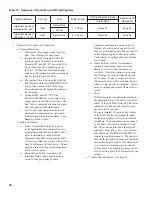
Table 10: Sequence of Operation and Wiring Diagrams
Ignition System
Country
Fuel
Boiler Sizes
Wiring Diagram Figure
Sequence of
Operation
Intermittent
Intermittent Ignition
(Honeywell EI - 24V)
USA
Natural Gas
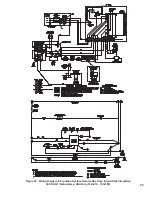
7 - 10 Sect.
Figure 31
Page 30
LP Gas
Intermittent Ignition
(EP-CSD-1 - 120V)
USA
Natural Gas
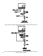
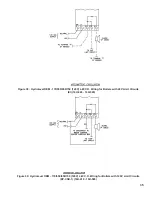
8 - 10 Sect.
Figure 35
Page 32
1. Honeywell EI Sequence of Operation
a. Normal Operation
i.
Thermostat or operating control calls for
heat. Vent Damper (if used) opens.
ii.
Ignition Module Terminals PV, MV/PV
and the Ignition Terminal are energized.
Terminals PV and MV/PV power the Pilot
Valve in the Gas Valve supplying gas to
the Pilot. The Ignition Terminal supplies
voltage to the Ignition Electrode creating an
electric spark to ignite the Pilot.
iii.
The sensing Circuit between the Q3481B
Pilot Burner and the IGNITION MODULE
proves the presence of the Pilot Flame
Electronically and the Ignition Terminal is
de-energized.
iv.
Terminals MV and MV/PV of the
IGNITION MODULE are energized and
supply power to the Main Gas Valve. The
Gas Valve is energized allowing main gas
flow, and ignition of Main Burners.
v.
Call for heat ends. Ignition module is de-
energized, de-energizing gas valve, and
extinguishing pilot and main flame. Vent
Damper (if used) closes.
b. Safety Shutdown
i.
Limit: Automatically interrupts power
to the Ignition Module and Gas Valve(s),
extinguishing pilot and main flame, when
water temperature exceeds set point.
Maximum allowable temperature is 250°F.
Circulator continues to operate with call for
heat, Vent Damper (if used) closes. Normal
operation resumes when water temperature
falls below set point.
ii.
Blocked Vent Switch: Automatically
interrupts main burner operation when
excessive flue gas spillage occurs.
Circulator continues to operate and Vent
Damper (if used) remains open with call
for heat. If blocked vent switch is activated
do not attempt to place boiler in operation.
Correct cause of spillage and reset blocked
vent switch.
iii.
Flame Roll-out switch: Automatically
interrupts main burner operation when
flames or excessive heat are present in
vestibule. Circulator continues to operate,
Vent Damper (if used) remains open with
call for heat. Control is single use device.
If flame roll-out switch is activated, do not
attempt to place boiler in operation. Correct
cause of spillage and replace flame roll-out
switch.
iv.
Pilot
– Pilot failure can occur during the start-up or
the operating cycle of the boiler. Any pilot
failure of the Q3481B Electronic Pilot, after
ignition of pilot flame will close the main
gas valve in 0.8 seconds.
– For approximately 90 seconds after failure
of the Q3481B pilot, the module through
the ignition terminal will try to reestablish
pilot flame. If no pilot flame can be sensed
by the flame rod circuit, terminals PV and
MV/PV are de-energized and the module
will lock out on safety. Five to six minutes
after shutdown, the IGNITION MODULE
restarts the ignition sequence. The ignition
trial, shutdown, and wait sequence continues
until either the pilot lights or the Thermostat
is set below room temperature (to end the
call for heat). The ignition sequence can be
reset by setting down the Thermostat for one
minute.
c. Trouble Shooting Guide. See Page 48.
Содержание 16H-340
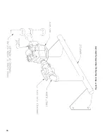
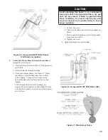
Страница 11: ...11 Figure 6 Flame Roll out Switch Installation Figure 7 Burner Burner Access Panel Installation ...
Страница 13: ...13 Figure 8 Jacket Assembly ...
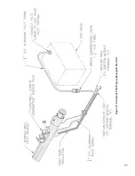
Страница 14: ...14 Figure 9 EP CSD 1 Control Installation ...
Страница 16: ...16 Figure 11 Main Gas Piping Intermittent Ignition EI ...
Страница 17: ...17 Figure 12 Schematic Pilot Piping Honeywell EI USA ...
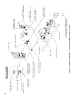
Страница 18: ...18 Figure 15 Schematic Gas Piping EP CSD 1 Control System 16H 410 16H 505 ...
Страница 31: ...31 Figure 31 Wiring Diagram Honeywell EI USA Intermittent Circulation 16H 340 16H 510 MegaStor Relay MegaStor ...
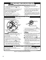
Страница 37: ...37 Figure 41 Operating Instructions EI ...
Страница 47: ...47 Honeywell EI Trouble Shooting Guide ...
Страница 48: ...48 THIS PAGE LEFT BLANK INTENTIONALLY ...
Страница 58: ...58 ...
Страница 60: ...60 ...

