


44
F.
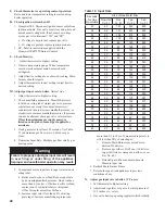
Clean Combustion Chamber
by vacuuming. Exercise
care to avoid damaging Base Insulation.
G.
Install Burners
by reversing procedures used to
remove burners. Verify Main Burners are properly
located on support bracket in Base Rear Panel, seated
on Main Burner Orifices, and secured with hitch pin
clips. Verify Main Burner with Pilot Bracket is in
proper location. See Table 13.
H.
Lubrication.
Manufacturers Instruction should be
followed on all parts installed on boiler requiring
lubrication. This includes type of lubricant to be used,
frequency of lubrication, and points to lubricate.
I.
Check operation.
Refer to Section VIII: System Start-
up.
Boiler Model
Pilot Located Between Burners*
16H-340
6 & 7
16H-410
6 & 7
16H-460
7 & 8
16H-505
8 & 9
*
Burners numbered left to right as viewed from front of boiler.
Table 13: Pilot Burner Location
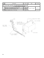
Figure 48: Boiler Flueway Cleaning
Содержание 16H-340
Страница 11: ...11 Figure 6 Flame Roll out Switch Installation Figure 7 Burner Burner Access Panel Installation ...
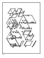
Страница 13: ...13 Figure 8 Jacket Assembly ...
Страница 14: ...14 Figure 9 EP CSD 1 Control Installation ...
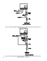
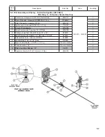
Страница 16: ...16 Figure 11 Main Gas Piping Intermittent Ignition EI ...
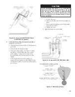
Страница 17: ...17 Figure 12 Schematic Pilot Piping Honeywell EI USA ...
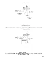
Страница 18: ...18 Figure 15 Schematic Gas Piping EP CSD 1 Control System 16H 410 16H 505 ...
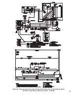
Страница 31: ...31 Figure 31 Wiring Diagram Honeywell EI USA Intermittent Circulation 16H 340 16H 510 MegaStor Relay MegaStor ...
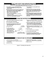
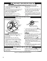
Страница 37: ...37 Figure 41 Operating Instructions EI ...
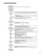
Страница 47: ...47 Honeywell EI Trouble Shooting Guide ...
Страница 48: ...48 THIS PAGE LEFT BLANK INTENTIONALLY ...
Страница 58: ...58 ...
Страница 60: ...60 ...


